
- Optima MR450w BASE 1.5T System Service Methods
- 5690012-2EN Revision 3
- 00000018WIA300FFD20GYZ
- id_131062943.0
- Aug 29, 2019 1:57:11 AM
1.5T HD 3-Channel Shoulder Coil Setup for MCQA Test
Prerequisites
| Required persons | Preliminary requirements | Procedure | Finalization |
|---|---|---|---|
| 1 | Not Applicable | 15 minutes | Not Applicable |
| Item | Quantity | Effectivity | Part number | Manufacturer |
|---|---|---|---|---|
| Phantom Positioner | 1 | - |
2375136-3 | - |
| 1.5T TLT Head Sphere (Green) | 1 | - |
46–265826G6 | - |
| Condition | Reference | Effectivity |
|---|---|---|
|
The coil configuration name HD Shoulder must be installed to run this tool. | - | - |
About this task
Follow this process to prepare for the automated SNR test using the1.5T 3ch Shoulder Coil with P connector by GE, catalog M7001NE.
Procedure
- Insert the Flat Filler Panel into the magnet end of the table.
Figure 1. Flat Filler Panel 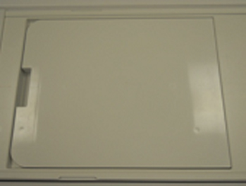
- Place the phantom positioner on the table, place coil on it,
and connect the coil cable to P2 port.Note:If the phantom positioner (2375136-3) is newly orderd as FRU, remove the extra parts at the bottom and make the bottom plate flat.
Figure 2. Remove bottom parts 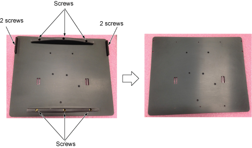 Note:
Note:Assemble the phantom positioner per following steps.
-
Assemble the two tall large diameter posts (with small diameter posts on top) to the phantom positioning plate using the brass screws provided. The two tall large diameter posts will fit into the two large diameter pockets at the head end of the plate.
-
Assemble the three small diameter posts (with angled top) to the phantom positioning plate using the brass screws provided. These three posts have the mounting holes offset from the center of the rod so they can only be assembled in the three holes in the plate that have the corresponding offset mounting holes.
-
Assemble the short large diameter post (with small diameter posts on top) to the phantom positioning plate using the brass screws provided. The short large diameter post fits into the remaining pockets in the center of the positioning plate.
Figure 3. Assemble the phantom positioner 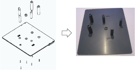
-
- Insert the phantom into the coil, then guide the coil onto the
phantom positioner pins (the holes in the coil frame will accept the
positioner pins).
Figure 4. Phantom Positioner, Coil, and Cable Connection on Flat Table 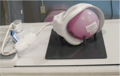
- Landmark on the coil crosshairs.
Figure 5. Landmarking on Coil 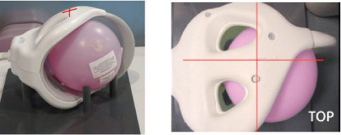
Proceed to the Multi-Coil Quality Assurance Tool procedure.Notice Note:Select “1.5T_HD_Shoulder_Array_by_GE” for Current Coil field.
Figure 6. MCQA Tool Menu 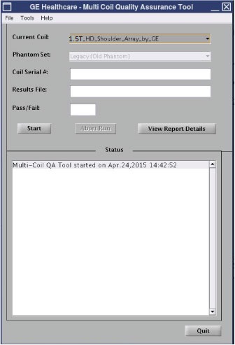
Finalization
No finalization steps.