
- Optima MR450w BASE 1.5T System Service Methods
- 5690012-2EN Revision 3
- 00000018WIA30EE0F20GYZ
- id_131067993.0
- Aug 29, 2019 1:57:16 AM
1.5T 8 CH Body Coil Cable Replacement
Prerequisites
| Required persons | Preliminary requirements | Procedure | Finalization |
|---|---|---|---|
| 1 | Not Applicable | 30 minutes | Not Applicable |
| Item | Quantity | Effectivity | Part number | Manufacturer |
|---|---|---|---|---|
| Standard Tool Set | 1 | - | - | - |
| Item | Quantity | Effectivity | Part number | Manufacturer |
|---|---|---|---|---|
| Cable Assembly | 1 | - |
2417162 | - |
About this task
This procedure will replace the cable assembly on the 1.5T HD 8CH Body Array Coil (P/N: 2415366) by GE/USAI, Catalog Number M3335MC.
Procedure
- Unplug the Anterior Cable Interface Box (Labeled with UP) from
the Anterior Body Array Coil as shown in Figure 1.
Figure 1. Removal of Anterior Cable Interface 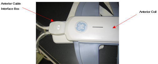
- Remove all the 8 screws form the lower Posterior Coil cover
as shown in Figure 2. Remove the cover after removing
the screws.
Figure 2. Removal of 8 Screws from Posterior Coil 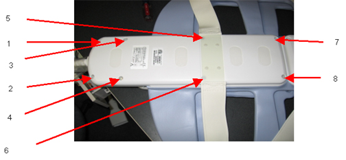
- Remove all the four screws as shown in Fig 3 below; Unplug the
RF cables labeled with CH5-CH8 and DC PIN Header Connector carefully
as shown in the Figure 3.
Figure 3. Posterior Coil RF Cable and DC Wire Removal 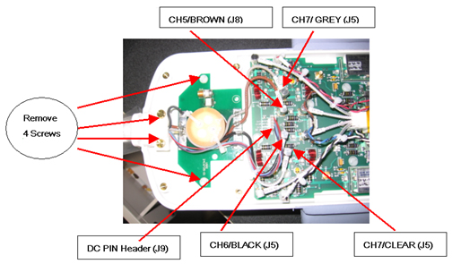
Finalization
No finalization steps.