
- Optima MR450w BASE 1.5T System Service Methods
- 5690012-2EN Revision 3
- 00000018WIA3063DD20GYZ
- id_131068465.0
- Feb 21, 2021 9:13:24 PM
1.5T 12-Channel Body Array Coil Cable Replacement
Prerequisites
| Required persons | Preliminary requirements | Procedure | Finalization |
|---|---|---|---|
| 1 | Not Applicable | 30 minutes | Not Applicable |
| Item | Quantity | Effectivity | Part number | Manufacturer |
|---|---|---|---|---|
| Standard Tool Set | 1 | - | - | - |
| Item | Quantity | Effectivity | Part number | Manufacturer |
|---|---|---|---|---|
| HDx System Cable | 1 | - |
2417328 | - |
| P-connector System Cable FRU | 1 | - |
2424308 | - |
| ||||||||
Cable Removal
Procedure
- Remove the 8 screws from the cover at the pelvic end of the
coil. There are two screws located under the strap. See Figure 1.
Figure 1. Back of Posterior 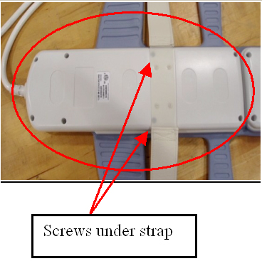
- Unscrew the cable clamp. See Figure 2.
Figure 2. Screws at Cable Clamp 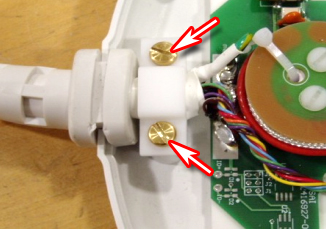
- Locate and disconnect all RF cables coming from the cable trap.
See Figure 3.
Figure 3. Disconnect Indicated RF Cables 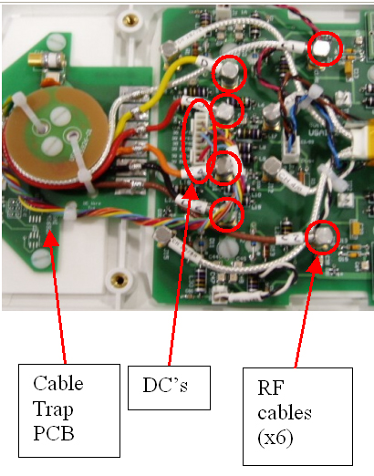
- Remove the cable from the coil. See Figure 4.
Figure 4. Posterior Cable Removal from Coil 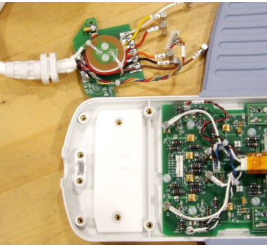
Cable Replacement
Finalization
Finalization
If available, perform Multi-Coil Quality Assurance (MCQA) Tool to ensure that the coil still operates properly, otherwise perform the Surface Coils SNR Test.