
- Optima MR450w BASE 1.5T System Service Methods
- 5690012-2EN Revision 3
- 00000018WIA30131F20GYZ
- id_131067233.0
- Aug 29, 2019 1:57:32 AM
HD 8Ch Foot Ankle Coil Troubleshooting Tips
| Required persons | Preliminary requirements | Procedure | Finalization |
|---|---|---|---|
| 1 | 0 minutes | 60 minutes | 0 minutes |
| Item | Quantity | Effectivity | Part number | Manufacturer |
|---|---|---|---|---|
| Digital Volt Meter | 1 | - | - | - |
| Condition | Reference | Effectivity |
|---|---|---|
|
The following coil configuration names must be installed to run this tool: HD Foot Ankle | - | - |
The following tips can be used to troubleshoot common problems with the 1.5T HD 8Ch Foot Ankle by Invivo, catalog M3340CD.
Receiving No Signal
You are unable to pre-scan or are scanning and yet receiving no signal.
Verify that you have selected the appropriate system coil selection. Refer to the Operators Manual for additional information.
Verify the green light above Port A is illuminated. This indicates the coil is properly plugged into the system.
Verify that the landmark is correct and that the cradle has not unlatched.
Verify that the scan locations and any FOV offsets are correct.
Perform a continuity check on the external cable (below). The continuity check must be performed by a GE authorized Service Engineer.
Verify that the coil is positioned with the cable exiting towards the bore and that the system and coil polarity match.
If you still cannot get a signal, try to scan (transmit and receive) with the body coil. For this test, be sure to remove the imaging coil from the magnet bore before you scan with the body coil. If you still receive no signal, the problem probably lies with your MR system. If the scan completes successfully, there is probably a problem with the Invivo coil. Contact GE for further assistance. If you are unable to scan with the substitute coil, there may be a system problem related to this particular coil type.
Image Quality
Image quality is not what you expect it to be given the parameters selected.
Review the selected protocol. If you are performing the Periodic Quality Assurance, be sure your protocol is identical to the protocol provided in your Systems Recommended Protocols. If you are performing diagnostic images, you may need to increase NEX or FOV.
Perform a continuity check on the external cable (below). The continuity check must be performed by a GE authorized Service Engineer.
Verify that there are no loops in the cables.
Verify that there are no metal or ferromagnetic objects close to the coil, patient or magnet (i.e., safety pin, hair pin).
Verify that the coil is properly positioned.
Verify that your center frequency is within the frequency adjustment range for your system.
Verify that the R1, R2 and TG values from the pre-scan are within normally expected ranges.
Cleaning the electrical contacts that connect the upper and lower halves with Isopropyl Alcohol and a cotton swab has been demonstrated to improve the coil’s SNR on occasion. If you have not done so already, perform a MCQA (Multi Coil Quality Assurance) Test. If the values you obtain do not fall within normal operating parameters, investigate this further by performing a phantom scan with the body coil. For this test, be sure to remove the imaging coil from the magnet bore before you scan with the body coil. If you still have the same problems, there is probably an MR system problem. If the body coil scan is satisfactory, acquire a scan using both another coil of the same type plugged into the same system port (port A). If the image quality is visibly improved, there may be a problem with the Invivo coil. Contact GE for further assistance. If the image quality still suffers, there may be a system problem related to imaging with this type of coil.
Artifacts
There is a black line or signal void on the image.
Verify that there is no metal present in the area being scanned in or on the patient.
Some or all of the images appear shaded or exhibit uneven signal or banding.
Confirm that no metallic objects are located nearby, outside the FOV. This is especially important on images utilizing Fat Saturation. If Fat Saturation is being used, verify that the CFA fine adjustment has been optimized.
External Cable Wear
The system will not recognize the coil or scan with the coil attached.
Perform the cable continuity check. As follows:
- RF Signal Channels Check: The center
pins of the System Connector receive coaxial connectors are extremely
fragile. Do not attempt to make any measurements at these center pins.
Note:
With the coil cable disconnected, use a multimeter to assure an open circuit condition exists between the designated pin and GND for each signal channel shown in Table 1.
Table 4. Coil Cable Connector Short Circuit and Open Circuit Check Signal Channel Coil Cable Connector Pin (Illustration 1) System Connector (Illustration 2) RF 1 A17 C1 RF 2 A15 C2 RF 3 A10 C3 RF 4 A21 C4 RF 5 A4 D1 RF 6 A8 D2 RF 7 B12 D3 RF 8 A13 D4 GND NOTE: The following pins are common to GND:
A2-A3, A5, A7, A9, A11-A12, A14, A16, A19-A20, A22-A23,
B1, B3-B6, B8-B11, B13-B18, B20-B21, and B23-B24.
K1-K8, M6, MC Shield Figure 1. Coil Cable Connector 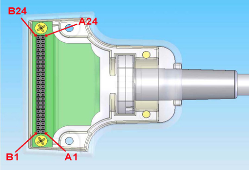
If one or more of the readings indicate a short, replace the cable. If all of the above readings indicate an open circuit condition, proceed to the PIN Diode Control Channels Check.
- MC bias line (DC line) Check: With the
coil cable disconnected, use a multimeter to determine continuity
between the designated pins for each signal channel below. Also verify
that the control pins are not shorted to GND.
Table 5. Coil Cable Connector Continuity Check Signal Channel Coil Cable Connector (Illustration 1) System Connector (Illustration 2) MC bias 1 A18 J1 MC bias 2 B22 J2 MC bias 3 B2 J3 MC bias 4 B19 J4 MC bias 5 A6 J5 MC bias 6 B7 J6 MC bias 7 A1 J7 MC bias 8 A24 J8 GND NOTE: The following pins are common to GND:
A2-A3, A5, A7, A9, A11-A12, A14, A16, A19-A20, A22-A23
B1, B3-B6, B8-B11, B13-B18, B20-B21, and B23-B24.
K1-K8, M6, MC Shield Figure 2. System Connector 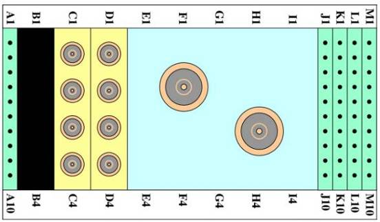
If one or more of the readings are > 3 ohms, replace the coil cable. If all readings are < 3 ohms, proceed to the PIN Diodes Check.
- PIN Diodes Check With the coil cable connected to the coil,
use a multimeter to measure the diode drop across the coil connector
pins as detailed below. Use the System Connector illustration above
for pin identification while performing this procedure.
Table 6. Pin Diode Expected Readings System Connector Positive Lead Negative Lead Reading (V) J1 GND [MC Shield] 1.7 ± 0.2 GND G1 J1 Open J2 GND [MC Shield] 1.7 ± 0.2 GND G2 J2 Open J3 GND [MC Shield] 1.7 ± 0.2 GND G3 J3 Open J4 GND [MC Shield] 1.7 ± 0.2 GND G4 J4 Open J5 GND [MC Shield] 1.7 ± 0.2 GND G5 J5 Open J6 GND [MC Shield] 1.7 ± 0.2 GND G6 J6 Open J7 GND [MC Shield] 1.7 ± 0.2 GND G7 J7 Open J8 GND [MC Shield] 1.7 ± 0.2 GND G8 J8 Open
Mechanical Parts Wear
Inspect the coil for visible signs of wear. If the coil housings will not seat with each other or if the latch mechanism will not work properly, contact Service.
Finalization
No finalization steps.