
- Optima MR450w BASE 1.5T System Service Methods
- 5690012-2EN Revision 3
- 00000018WIA3090DD20GYZ
- id_131062543.0
- Aug 29, 2019 1:57:10 AM
1.5T 3-Channel Shoulder Coil FRUs and Cable Replacement
1.5T 3-Channel Shoulder Coil FRUs
| Item | Description | GE Part Number |
| 1 | FRU Coil, 1.5T Shoulder | 5498927 |
| 2 | FRU, 1.5T Kizuna Shoulder Cable | 5015498 |
| 3 | Shoulder Coil Phantom Positioner | 2375136-3 |
| 4 | Shoulder Coil Patient Comfort Pad | 2375136-5 |
| 5 | FRU, Spacer pad, Shoulder | 2413827 |
| 6 | Strap and Pin FRU, Shoulder Coil | 5370109 |
| 7 | Shoulder Coil Vinyl Repair Kit | 5440960 |
Shoulder Cable Replacement
Follow this procedure to replace the system cable on the Shoulder Coil. Before beginning this procedure, remove the coil from the magnet room. Wear an ESD wrist strap to avoid electrostatic discharge.
Personnel Requirements
| Required Persons | Procedure Timing |
| 1 | 45 minutes |
Preliminary Requirements
Tools and Test Equipment
| Item | Qty |
| Standard Tool Set (P/N 5112581) | 1 |
| ESD Wrist Strap | 1 |
Parts
| Item | FRU Part Number | Qty | |
| 1.5T Shoulder Coil System Cable | See FRU List | 1 | |
Procedure
-
Remove the nine screws holding the cover on the unit.
Figure 1. Remove 9 Screws 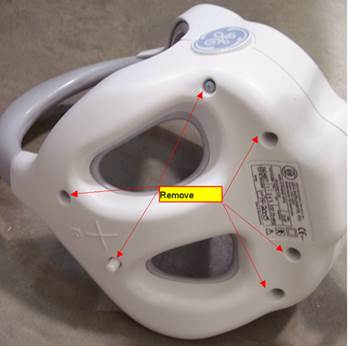
-
Disconnect the RF cables and the DC wires from the feed boards.
Figure 2. Disconnect RF Cables 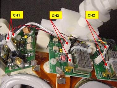
-
Remove two screws on the clamp of strain relief.
Figure 3. Remove 2 Screws on Clamp of Strain Relief 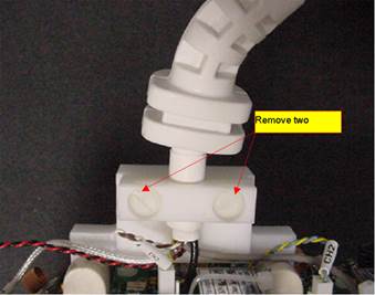
-
Remove the cable from the coil.
Figure 4. Cable with Cable Clamp to Coil 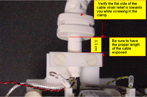
-
Install New Cable in Coil. Attach the cable with the cable clamp to the coil.
-
Connect the DC wires and RF cables
Table 2. Connection RF Wires Color Label Black CH3 Gray CH2 Silver CH1 DC Wires Blue and Yellow (Twisted) CH2 Red and Black (Twisted) CH1 Brown and White (Twisted) CH3
Finalization
Run the MCQA Tool to verify the Shoulder Coil operates properly.