- Topic ID: id_17423478
- Version: 3.0
- Date: Dec 3, 2019 2:00:14 AM
Touch Switches Assembly Replacement
Prerequisites
Procedure
- notice
- Move the cradle to the OUT mechanical limit position by hand.
- Raise the Table to its highest position.note: If the Table up/down movement is inoperative, use the service power cable to raise the Table (refer to Enforced Table Elevation).
- "Remove power from Table by turning off “120VAC”, “Axial Drive” and “HVDC” switches on the service switch panel."
- Remove the following cover from the Table:
-
Top Cover R / L (Refer to Table Covers Removal)
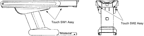
Figure 1. Touch SW1 / SW2 Assembly Location
-
- Remove the Touch SW1/SW2 Assy from the Table top cover.
- Thread the Touch SW1/SW2 cable connector through the cable hole in the Table top cover, and attach the new Touch SW1/SW2 Assy to the Table top cover, then connect the Touch SW1/SW2 cable connector.
- Restore the Table to original configuration.
 |
Finalization
- Verify that Touch SW1/SW2 Assy is operating normally.