- Topic ID: id_15460151
- Version: 4.0
- Date: Jan 20, 2020 8:32:15 PM
RIM IMS Cover Set Replacement
Prerequisites
Overview
This procedure describes the steps necessary to replace from FRP*¹ IMS covers to RIM*² IMS covers.
1 Preparation
Procedure
- Raise the Table to its highest position.
- Move the Cradle and IMS to OUT limit position.
- Remove power from Table by turning off 120VAC, Axial Drive and
HVDC switches on Service Switch Panel.
2 Replacement Procedure
Procedure
- Remove the following Table covers:
-
IMS Side Covers (Left/Right)
-
IMS Rear Cover
-
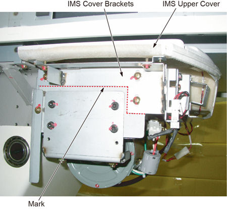
- Mark the position of IMS cover bracket on both sides for installation
of new bracket.
Figure 1. IMS Cover Bracket Position
- Disconnect the cable connectors of the tape switches and touch sensors.
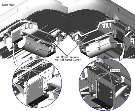
- Remove six (6) screws holding the both sides of the IMS cover
brackets.
Figure 2. Six (6) screws of the IMS Cover Bracket
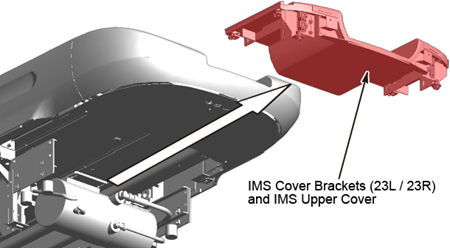
- Remove the IMS cover bracket with the IMS upper cover.
Figure 3. IMS Cover Bracket and IMS Upper Cover Removal
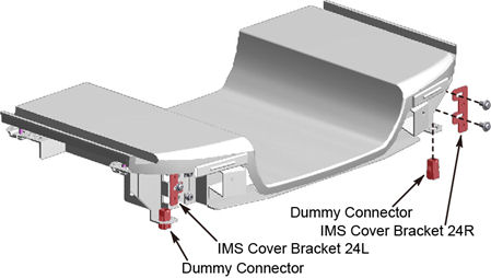
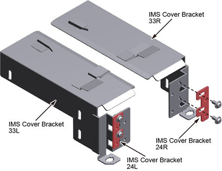
- Remove the IMS cover brackets (24L and 24R), and two dummy connectors
from the removed IMS cover bracket.
Figure 4. IMS Cover Bracket (24L and 24R) and Dummy Connectors
- Transfer the IMS cover brackets (24L and 24R) to the new IMS
cover brackets (33L and 33R), and temporarily tighten the two screws
on the left and right sides of the brackets.
Figure 5. IMS Cover Bracket 24L and 24R Attachment
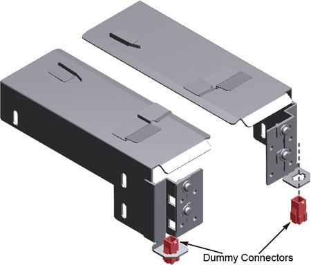
- Transfer the dummy connectors to the new IMS cover brackets
(33L and 33R).
Figure 6. Dummy Connector Attachment
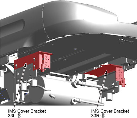
- Install the IMS cover bracket (33L and 33R) to fit the mark
on the table frame.
Figure 7. IMS Cover Bracket (33L and 33R) Installation
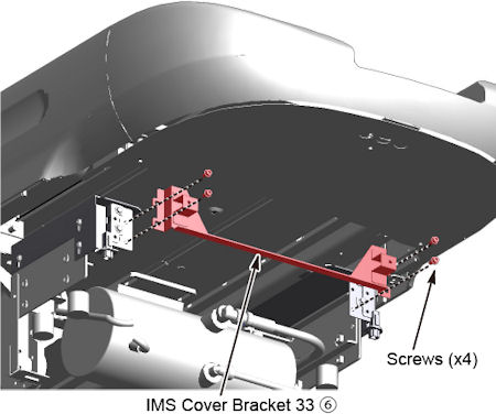
- Attach the IMS cover bracket 33 to the brackets (33L and 33R).
Figure 8. IMS Cover Bracket 33 Attachment
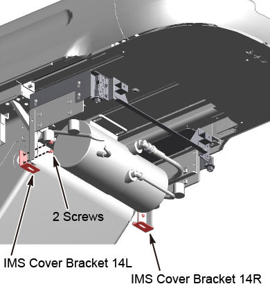
- Remove the IMS cover bracket (14L and 14R).
Figure 9. IMS Cover Brackets (14L and 14R) Removal
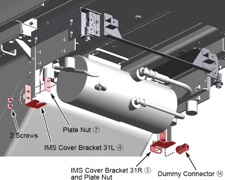
- Install the IMS cover brackets (31L and 31R) to the table frame
using plate nuts, attach the dummy connector to the bracket 31R.
Figure 10. IMS Cover Brackets (31L and 31R) Installation
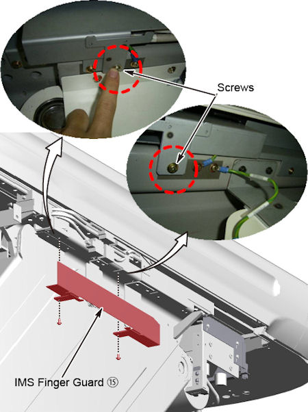
- Install the IMS finger guard to the left side of the table.
Figure 11. IMS Finger Guard Installation
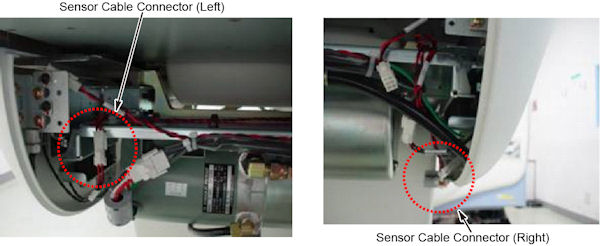
- Instal the new IMS Side Covers (Left/Right).
- Connect the cable (⑩) to J120 and touch sensors on IMS side
covers (J123 and J124).
Figure 12. Sensor Cable Connector
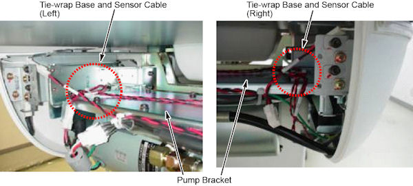
- Tie-wrap the sensor cable to the tie-wrap base on the pump bracket,
to remove excess slack in the cable
Figure 13. Sensor Cable and Tie-wrap Base
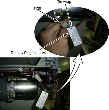
- Attach the IMS dummy plug label to the J120 connector of the
5120581-X cable using a tie-wrap (⑪).
Figure 14. IMS Dummy Plug Label Attachment
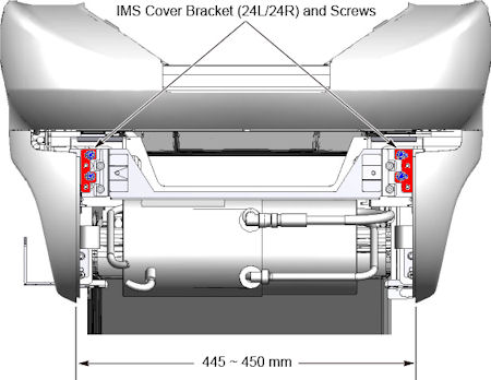
- Move the IMS cover brackets (24L and 24R) to set the position
of IMS side covers as shown in illustration blow, and tighten the
four screws on the left and right side IMS cover brackets.
Figure 15. Position of IMS Side Covers
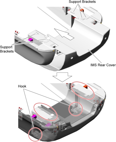
- Install the new RIM IMS rear cover.
- Slide the IMS rear cover hook into position
- Tighten the two screws.
Figure 16. IMS Rear Cover Installation
3 Finalization
No finalization steps.