- Topic ID: id_16158084
- Version: 1.0
- Date: Jul 7, 2018 4:41:50 PM
Operator Control Panel Replacement
Prerequisites
Overview
This procedure defines the steps necessary to replace the operator control panels on the gantry covers.
Procedure
- Remove gantry right side cover.
Refer to
- Turn OFF the Axial Drive, HVDC and 120 VAC switches on the gantry’s Service Switch Panel.
- Remove the gantry left side cover, top covers, scan window and front cover.
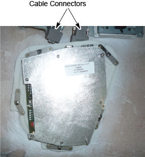
- Disconnect the two cables on the top of the control panel.
Figure 1. Gantry control panel
- Loosen five (5) screws that mount the control panel to the cover, and keep one hand on the control panel at all times to prevent it from dropping to the floor.
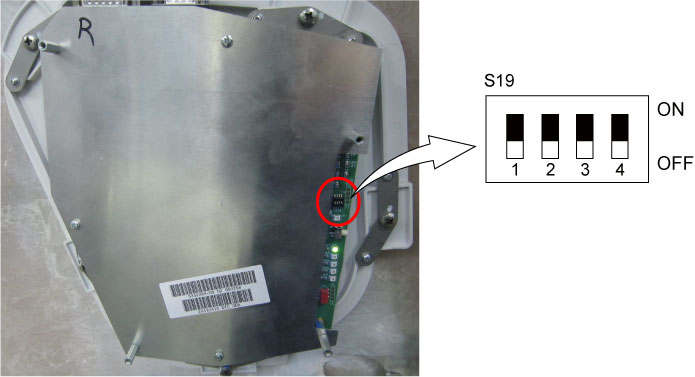
- Install the new control panel to the cover, and verify dip switch
S19 is OFF on the new control panel.
Figure 2. Dip Switch Setting
- Reconnect the two cables to the control panel.
- Install the gantry front cover, scan window, top covers, and
left side cover.
Refer to
- Enable 120 VAC HVDC and Axial Drive service switches from the service switch panel. Press the table drives enable button on the lower right corner of the service switch panel.
- Install the gantry right side cover.
Finalization
- Use the controls of the replaced panel to perform the table and gantry movement functions to ensure they work as expected.
- Perform a System Scanning Test from the Functional Checks menu of the service manual to ensure system operation.