Prerequisites
Overview
This procedure defines the replacement process for the Integrated Peripheral Controller (IPC) Board.
Procedure
- Make sure to follow all Lockout/Tagout requirements while performing
this procedure. Refer to Equipment Service - Lockout-Tagout-PPE procedure.
- Remove Gantry Base Covers as needed to access the IPC board.
- Disconnect all connections to the IPC Board.
- Remove the six bolts attaching the IPC Board to the Gantry.
- Set the IPC Board aside.
- Use the six bolts previously removed to attach the replacement
IPC Board onto the Gantry.
- Reconnect all connections to the IPC Board.
- Remove all installed Lockout/tagout devices.
- Restore power to the system. Refer to Equipment Service - Lockout-Tagout-PPE
procedure.
Finalization
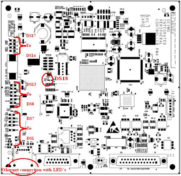
- To make sure the IPC board is functioning, an LED inspection
should be made on the board.
The LED configuration on the board should be as follows with
power on but no options connected to the options interface panels:
Figure 1. IPC board LED locations
- Install all removed Gantry base covers.