- Topic ID: id_16157879
- Version: 5.0
- Date: May 22, 2020 4:05:12 AM
GTCB Replacement
Prerequisites
Overview
This procedure covers replacement for GTCB, GTCB2 and GTCB3. GTCB3 can be replaced with both of GTCB and GTCB2 because GTCB3 is backward compatible. Replacement for GTCB3 and GTCB2 are the same as GTCB.
Procedure
- Raise the Table to maximum height.
- Perform this step if applicable:
(For Global PET/CT Table, with fixed position IMS) Move the Cradle to OUT limit position.
(For Global PET/CT Table) Move the Cradle and IMS to OUT limit position.
(For GT1700 and GT2000 Table) Move the Cradle and IMS to OUT limit position.
(For GT1700V Table) Move the Cradle to OUT limit position.
- Remove power from Table by turning off 120VAC, Axial Drive and HVDC switches on Service Switch Panel.
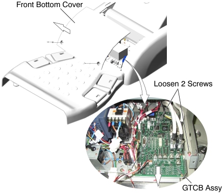
- Remove the Front Base Cover.
- Disconnect all cable connector from the GTCB Assy.
- Loosen 2 screws, and slide GTCB Assy with the bracket toward the Gantry, then remove it from the Table.
- Remove the existing GTCB Assy from the bracket, and attach the
new GTCB Assy to the bracket.
Figure 1. GTCB Assy Removal
- Install the new GTCB Assy with bracket in place, and tighten the 2 screws.
- Re-connect all cable connectors to the GTCB Assy.
Finalization
- Power up the Table from the Service Switch Panel.
- Perform the following:
Flashdownload (Wait approximately 2 minutes until GTCB firmware start up sequence completion before Flashdownload.)
Cradle Characterization Procedure according to Align,Setup, Cals ->Table.
- Elevation Characterization Procedure according to Align,Setup, Cals ->Table.
For Mechanical Characterization, peform following procedure.
- Start the Mechanical Characterization tool from the Calibration tab on the Common Service Desktop
- Select the CHARACTERIZE TABLE HEIGHT button from the interface.
- Follow the on-screen instructions.
- Turn off all 3 switches (Axial Drive, HVDC, 120VAC), and re-install the Table Covers.