- Topic ID: id_11038855
- Version: 4.0
- Date: Mar 6, 2020 10:02:03 PM
GTCB Assembly Replacement
Prerequisites
Procedure
- Move the cradle to the mechanical OUT limit position by hand.
- Raise the Table to its highest position.note: If the Table up/down movement is inoperative, use the service power cable to raise the Table (refer to Enforced Table Elevation).
- Remove power from Table by turning off 120VAC, Axial Drive and HVDC switches on Service Switch Panel.
- Remove the Rear Bottom Cover.
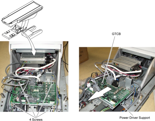
- Remove 4 screws, and slide the power driver support toward the
Gantry.
Figure 1. Location of GTCB Assembly
- Disconnect all cable connectors from the GTCB assembly.
- Remove 8 screws, and remove the GTCB assembly from the power driver support.
- Install the new GTCB assembly by referring toStep 7 through Step 6.
- Re-connect all cable connectors to the GTCB assembly.
Finalization
- Power up the Table from the Service Switch Panel.
- Perform the following:
- Flashdownload (Wait approximately 2 minutes until GTCB firmware start up sequence completion before Flashdownload.)
- Cradle Characterization Procedures according to Align, Setup, Cals -> Table.
- Elevation Characterization Procedures according to Align, Setup, Cals -> Table.
- For Mechanical Characterization, perform following procedures.
- Start the Mechanical Characterization tool from the Calibration tab on the Common Service Desktop.
- Select the CHARACTERIZE TABLE HEIGHT button from the interface.
- Follow the on-screen instructions.
- Turn off all 3 switches (Axial Drive, HVDC, 120VAC), and re-install the Table Covers.