- Topic ID: task_uvq_542_5jb
- Version: 2.0
- Date: Dec 10, 2019 2:30:53 AM
Cradle Belt Tension Adjustment
Prerequisites
Procedure
- Move the table to the proper height position where the cradle can be inserted into the Gantry bore.
- Move the cradle to the mechanical OUT limit position by hand.
- Remove power from Table by turning off "120VAC", "Axial Drive" and "HVDC" switches on the service switch panel.
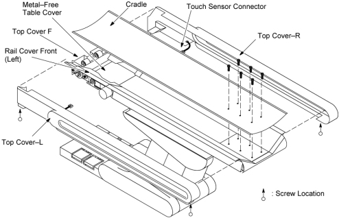
- Remove the following cover and components from the Table:
- Top Cover R / L
- Top Cover F
- Cradle
- Metal-Free Table Cover
- Rail Cover Front (Left/Right)
Figure 1. Table Covers and Components Removal
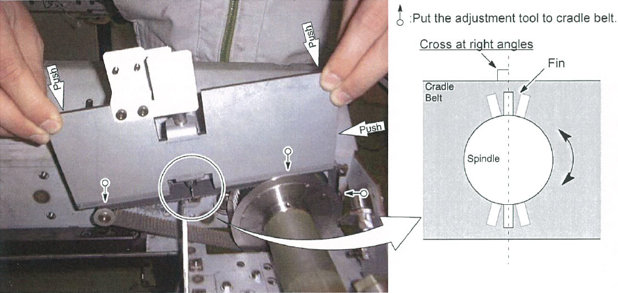
- Check the cradle belt tension:
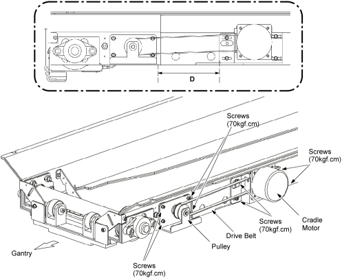
- Adjust the cradle belt tension:
- Measure the distance 'D' (between the pulley and cradle motor).
- Loosen 4 screws that fasten the cradle motor to the Table frame.
- Slide the cradle motor toward the Gantry, to remove tension from the drive belt.
- Loosen 4 screws that fasten the pulley to the Table frame.
- Slide the pulley toward the Gantry, to remove tension from the cradle belt.
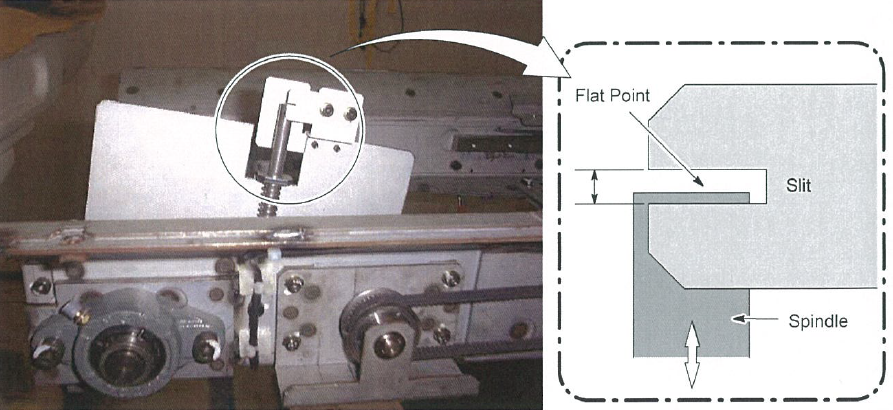
- Adjust position of the pulley so that the flat point of the spindle is in the narrow slit (see Figure 3), and fix the pulley.
- Adjust position of the cradle motor to meet the 'D' recorded at step a., and fix the cradle motor.
- Restore the Table to original configuration.
Figure 4. Release Belt Tension
Finalization
- Install the covers in the reverse order of removal.