- Topic ID: id_17423385
- Version: 5.0
- Date: May 22, 2020 4:06:01 AM
Options Inspection
 |
|

|
|
1 Ceiling Mounted Component Bolts
These instructions refer to any GE-supplied ceiling-mounted object.
-
Acquire and place an appropriately-sized ladder under the ceiling-mounted component.
-
Remove any ceiling covers and ceiling tiles to access the pedestal base.
note:For the more detailed steps, please refer to the option installation manual.
-
Verify that the mounting plate and pedestal base are securely bolted.
-
If the mounting plate is loose, inform the customer to have their contractor check and repair the structural integrity.
-
If the pedestal base is tight, confirm that the bolts that were marked at install have not moved.
-
If the bolts were not marked at install, mark the bolt and plate using a permanent marker.
-
If any loose hardware is detected, use a torque wrench and re-secure. Add a new visual inspection mark.
-
-
Inspect the arm assembly and confirm that the assembly is tight.
-
Check the safety spring (1) exists and the retention screws (3x2) at the arm assembly joint are tight. Tighten any loose hardware . The retaining clip (2) is very important to hold the arm assembly.
Figure 1. Arm Assembly Joint
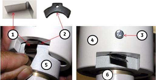
1 Safety Spring 2 Retainig Clip 3 Retaining Screw (For Safety Spring and Retainig Clip) 4 Safety Collar 5 Receptacle 6 LCD Monitor Mount Post (Receiver) -
Check the component end and confirm that the mounting hardware is tight. Tighten any loose hardware.
-
Reinstall all removed covers and ceiling tiles and store the ladder.
2 Injector Inspection
Follow the vendor-supplied installation manual for your Nemoto injector.
Non-Nemoto injectors are not covered. This is the customer's responsibility.
3 Cardiac Option Inspection
3.1 Cardiac Monitor Setup
Before you begin, verify that the following cords/cables are connected to the gantry option panel:
-
Turn on the monitor.
-
Follow the monitor self-test setup procedure using the document shipped with the system.
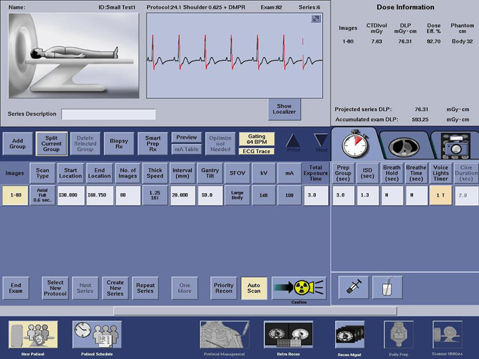
3.2 Cardiac Scan Setup for Functional Check
-
On the setup screen, enter the following selections:
-
New Patient: GE Test
-
On the screen, select the tab (see Figure 2).
-
On the tab, select Chest.
-
-
On the scan monitor (on the dark blue bar) select: Gating On
-
Look for the following diagnostics to display (see Figure 3):
-
Heart rate on the gantry display board
-
Cardiac pulses shown on the screen
-
Gating BPM displayed on the screen
-
ECG trace highlighted on the screen
-
Figure 2. Protocol Selection Screen
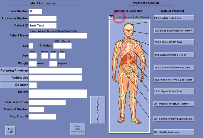
Figure 3. Cardiac Scan Screen