- Topic ID: id_17422975
- Version: 3.0
- Date: Apr 22, 2019 12:56:00 AM
Merc40 Detector Theory
1 Overview
Merc40 Detector is new Detector sub system designed for Cj M40 system. The key component is Chiclet and VCS (FPGA), that work as transducer of X-ray to electron and A/D converter. The device outputs digital signal to FPGA and send the data to CDCB. This section explains this new Detector subsystem.
2 Difference from Saturn DAS subsystem
Figure 1. DAS System comparison
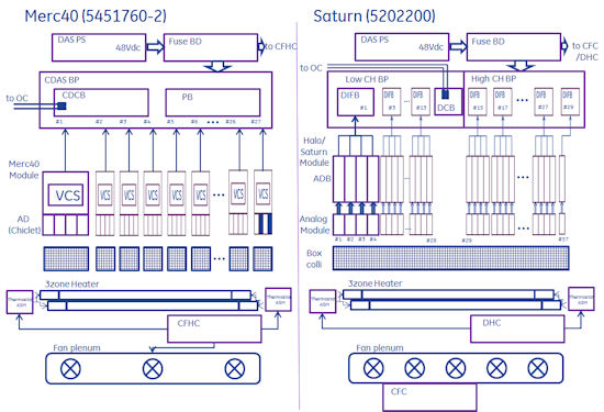
Merc40 DAS is configured by the following components.
-
27 Detector modules (last one is special module)
-
27 Modular collimator
-
27 VCS Cables
-
One Back plane
-
CDCB (DAS Control Board)
-
PB (Power Board)
The key component is Chiclet and VCS used in Detector module. The function of Chiclet and VCS is equivalent to Analog module, ADB and a part of DIFB. Also firmware downloading during power up sequence is not needed. That enables to detect fault module independently in any failure case. Also each connector type (used on Back plane) is very precise design, and it’s difficult to have bad contact partially.
VCS Cable is used for each Module and Backplane connection and the following signals are on the cables.
-
Power Supply (+1.8VDC, +3.3VDC) from Power Board (PB) via Back plane.
-
Clock Input
-
Digital Control Input (Trigger and others)
-
Digital Data output
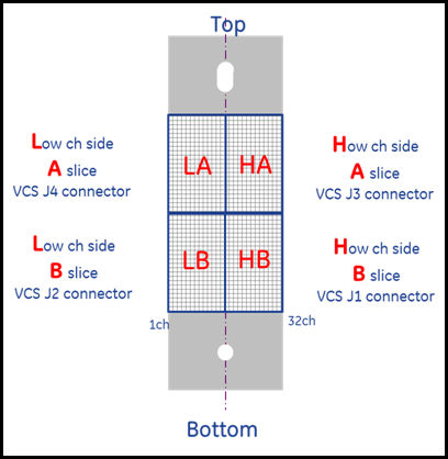
One detector module contains 4 Chiclets, and 2 Chickets are used as pair for 64 channel coverage (one Chiclet covers 32 channel area). Physically there are 27 detector module is used, and 53 Chiclet pair are used. Then last module has only 2 Chiclet and dummy Chiclet is used for remaining 2 Chiclet area. The module name is different from other modules,. called as Ref27. But it does not mean that this module is used only for reference channel data.
Figure 2. Merc40 Detector design
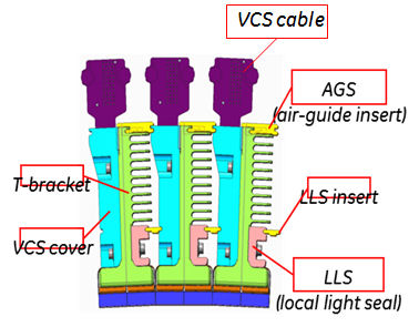
Figure 3. Chiclet allocation map in detector module
Basically module z-axis alignment is not needed. The Z axis module position is determined by T-Frame and detector rail (with modular collimator exactly). Therefore the usage of zalignmentwizard in FRDM Wizard is used only to confirm the module position is in specification or not.
Modular collimator is new design strategy in order to prevent whole detector replacement and manufacturability improvement. Saturn DAS uses Box collimator and it may be damaged by Detector module replacement. Merc40 modular collimator is protected by carbon plate at the both side of surface, then very rare case it will be damaged. Even if it’s damaged, replacement at module level is enable, it prevent from whole detector replacement. Modular collimator is adjustable for Z-axis. It’s set as FRU, but the replacement requires special technique for alignment. It’s recommended to replace it with OLC or engineering team.
3 Detector Channel Map
-
The following shows the Merc40 detector channel usage.
-
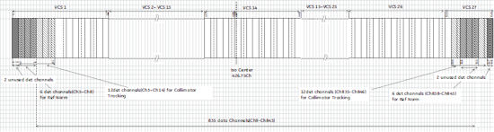
Active Ch# 835 (#9 to 843ch)
-
Reference Ch# 6 for each end (#3 to 8, #838 to 843)
-
Collimator Tracking Ch# 12 for each end (#3 to 14, #835 to 846)
-
Unused Ch# 2 for each end (#1 to 2, #847 to 848)
-
ISO Center: 426.75ch.
Figure 4. Detector channel map
4 Bad Channel Condition
The following illustration shows the Bad Channel information. Bad channel is checked in the following case.
-
Collimator Cal. (Detailed Cal. and FRDM Wizard)
-
FastCal.
Figure 5. Bad Channel condition for X direction.
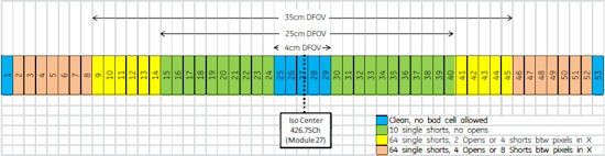
Figure 6. Bad Channel condition for Z direction
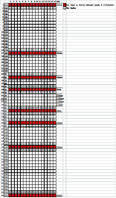
Requirement of Bad Channel:
-
No short between pixels in the x-direction is in Rows 4, 8, 16 or 32 (both A and B-sides).
-
No open in Rows 3-5, 7-9, 15-17, 31-32 (both A and B-sides).
5 Merc40 Thermal Cooling design
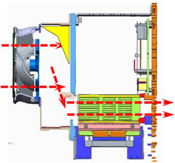
Figure 7. Thermal Air flow
6 Power and Signal connection
Refer to CDAS Theory in this SV manual.