- Topic ID: id_17422960
- Version: 6.0
- Date: Sep 26, 2020 10:10:13 PM
Equipment Service - NGPDU
This procedure supports the following NGPDU:
-
NGPDU-6, -60
-
NGPDU-80
-
NGPDU-81
Figure 1. Full Size Illustration: NGPDU-60 Front & Rear (exposed view)
pdu front and rear block.pdfFigure 2. NGPDU-60 Front & Rear (exposed view)
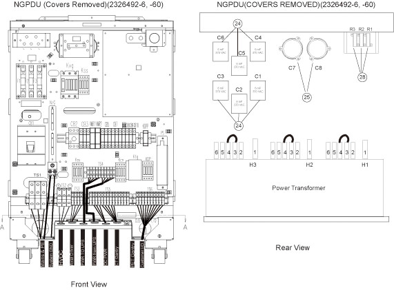
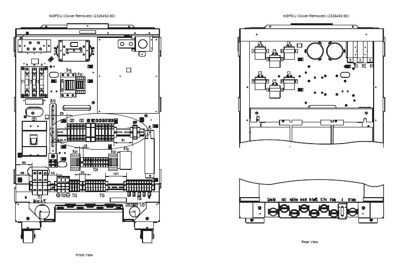
Figure 3. Full Size Illustration: NGPDU-80 and -81 Front & Rear (exposed view)
NGPDU cover removed.pdfFigure 4. NGPDU-80 and -81 Front & Rear (exposed view)
The PDU must be de-energized prior to performing work on it. 100 Kilowatts of power exists in the PDU at various periods of time. Therefore, consider all points in the PDU as hazardous.
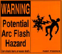
Figure 5. Arc Flash Hazard
 |
|

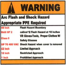
Figure 6. PPE Warning
1 Electrical
1.1 Potential Hazards
-
Axial drive power for gantry rotation (AC)
-
High voltage DC for X-ray generation (floating DC)
-
Distributed console, table and gantry power (AC)
1.2 Hazard Awareness Indicators
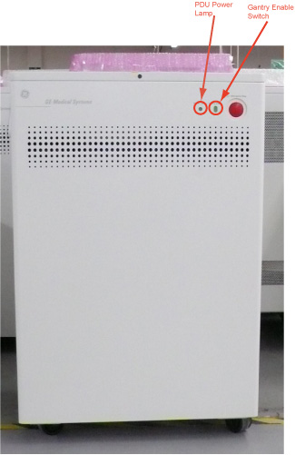
Two small power lamps are visible on the front cover. When illuminated, one lamp indicates power is present within the PDU. Another lamp is also a switch named “Gantry Switch”, which is used to control AC 120 V power for CT Gantry. See Figure 7.
Figure 7. PDU Power Lamp
1.3 Protected Service Outlets
The service outlet is protected by a circuit breaker. The outlet is located on the Terminal panel. See Figure 2.
1.4 Circuit Breakers and Switches
CIRCUIT BREAKERS
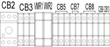
(For NGPDU-60) There are some circuit breakers in the NGPDU used to protect various parts of the system. See Figure 8.
CB2 - Axial Drive
CB3 - UPS Power Supplier
CB5 - CT Gantry Rotating Loads
CB7 - Operator Console Loads
CB8 - PET Gantry
CB9 - NGPDU Control Power Supply
CB10 - NGPDU Control Power Supply
Figure 8. PDU Circuit Breakers for NGPDU-60
(For NGPDU-80) There are some circuit breakers in the NGPDU used to protect various parts of the system. See Figure 9.
CB2 - Circuit Protection (Axial Drive).
CB3 - Full Winding Protection.
CB4 - CT Gantry Service Outlets.
CB5 - CT Gantry rotating loads.
CB6 - Table & CT Gantry Stationary Loads
CB7 - Operator Console Load
CB9 - VMR1, Control P.S Load
CB10 - VMR2
Figure 9. PDU Circuit Breakers for NGPDU-80
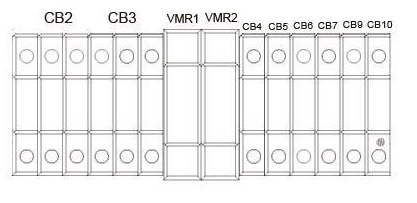
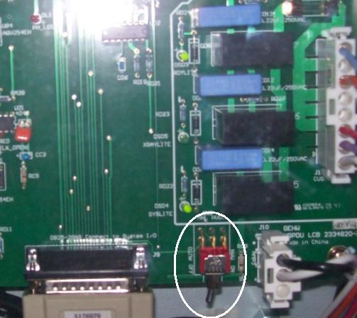
Figure 10. SWITCH 2 MNL_HVDC
 |
|
2 Mechanical
The PDU’s top cover is not hinged. To access the top of the PDU, loosen the top cover front retaining screw, then lift and remove the PDU top cover.