- Topic ID: id_17422955
- Version: 2.0
- Date: Nov 20, 2019 9:49:36 PM
Equipment Service - Gantry
1 General
With the gantry’s primary covers removed, secondary covers are used to help prevent accidental contact with electrical contacts. The most electrically dangerous area in the CT gantry is the exposed slip ring platter. The system should be tagged and locked out whenever the gantry covers are removed.
When the gantry is rotating, the left and right sides of the gantry are where objects are most likely to be ejected, if not properly fastened. IT IS IMPORTANT THAT ALL HARDWARE BE PROPERLY FASTENED (TORQUED) TO ITS PROPER SPECIFICATION.
Take the following precautions when working on, near or around the gantry:
-
Never wear loose clothing or jewelry. Clothing might become entangled in the rotating assembly and jewelry can short to high voltages.
-
Avoid standing near the rotating assembly when it is operational, to avoid being struck by the assembly or ejected objects. Always torque fasteners to their proper specification.
-
Avoid standing or kneeling near the slip ring platter. High voltages exist on the exposed rings. Always disable power to the rings by using the service switches before performing service.
-
Never put any part of your body into the gantry, unless the gantry is locked. Axial drive power must be disabled. If working on the tilt assembly, the tilt locking bracket should be installed, except when replacing the Hydraulic Tilt Assembly (instructions for inhibiting movement of the gantry for the Hydraulic Tilt Assembly are located in that replacement procedure).
-
Wear and use personal protection equipment.
-
Tag and lockout power at the main disconnect.
-
Apply Ergonomic principles when necessary. Understand your physical limitations and get help when necessary.
Always use and follow procedures described in your service documentation, when servicing this equipment. For additional information on clearance issues, see the Regulatory Clearance Quick Reference Guide.
2 Limited Access
The design allows service personal to adequately install, complete PM inspections, replace broken components, complete adjustments with power on, and troubleshoot the system without accessing the gantry from the left (non-tube change service) side while energized. When replacing components and performing service tasks that require access to gantry left-side components, all system power will be locked out at the A1 breaker.
The primary gantry left-side serviced components include TGPU, TGPU power supply, gantry stationary fan controller, gantry stationary 48V power supply, x-ray tube pump assembly, axial encoder, gantry home flag board, gantry tilt pot assembly, all system cables, left-side gantry E-stop box, and the gantry balance sensor board. All these are to be serviced in a non-energized state.
When Service Engineers are performing “Power On” energized-service tasks, including troubleshooting and adjustments, all tasks will be done without accessing the gantry left (non-tube change service) side. The Service Engineers will use newly designed hardware, software / firmware tools, and service procedures to complete all tasks from the front, back, or right side of the gantry. In addition, even those rooms that have access greater than 36” of clearance on the gantry non-tube change side, all service will be completed non-energized as described in this document.
Service access and egress will be restricted for all sites with less than 28” of left-side clearances, measured from the side cover to the obstruction or wall. “No Energized Service” labels will be visible on the TGPU cover. Standing or performing service tasks on the gantry’s left side while the system is energized will be considered a regulatory violation.
More information regarding regulatory requirements and siting requirements can be found in the Pre-Installation Manual for your system.
3 Electrical
3.1 Potential Hazards
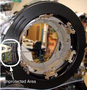
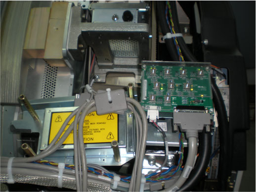
All un-insulated electrical contacts, including the slipring, have secondary covers in place to protect service personnel from accidental contact. Removal of any secondary cover exposes service personnel to potentially deadly voltages (see Figure 1).
All secondary covers must be in place before primary covers are installed and during routine service.
Figure 1. CT Gantry Slip Ring Platter Covers
Un-insulated high voltage areas in the brush-block area include:
-
High voltage DC for X-ray generation. Only measurement equipment isolated from ground can be used to measure HVDC on this system. Use of grounded measurement equipment can result in serious personal injury and/or equipment damage.
-
120VAC for power supplies.
3.2 Safety Awareness Indicators
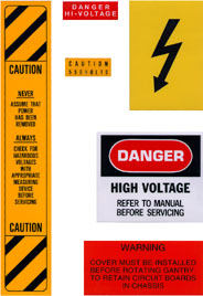
If a secondary cover can be removed and it potentially exposes a service person to an uninsulated electrical hazard, a warning label is applied to or near the secondary cover. In the gantry, voltage hazards in excess of 120VAC have been labeled. However, the 120VAC present in the gantry also is capable of causing electrocution. See Figure 2 for some of the label types used in the gantry.
Figure 2. Gantry Electrical Hazard Lables
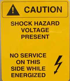
Special warning labels for a limited-access hazard are visible when the left-side cover is removed. See Figure 3.
Figure 3. Limited Access Warning Label
LAMPS & LEDS
There are a number of lamps/LEDs on the Service Switch Panel that indicate the functional state of the gantry. See Table 1 for a functional description.
The descriptions in the above table apply when the associated LED is lit.
3.3 Service Outlets and E-Stops
A number of features have been provided as means of disabling hazards at particular points in the gantry, for ease of service. This and the next few sections will describe these features.
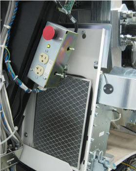
The E-Stop and Service outlets are located on both sides of the gantry on the stationary frame. The E-Stop is identified as a large red push button. The Service outlets are standard duplex 120VAC outlets. These are provided for ease of using AC powered test equipment near the gantry without requiring extension cords.
Figure 4. Gantry E-Stop and Service Outlets (Left Side of Gantry)
3.4 Service Switches
The service switches and circuit breakers described hereafter are not to be relied on as personal protection devices. They do not replace tag and lockout of main power to ensure personal safety. Switches and breakers are intended to only inhibit particular system functions and equipment operation. They do not eliminate or remove the electrical or mechanical hazards that exist. Because hardware can fail and defeat the functionality of these devices, only Lockout/Tagout ensures protection from unattended gantry rotation and electrocution. Be aware that not all power is removed on the gantry by use of these switches.
The Service switches are located on the right side of the gantry on the stationary base just above the rear cover cam latch. UP (enabled) is the normal operational position for these switches. The primary service safety switches are located across the top of the service switch panel.
Figure 5. Service Switch Panel Location
When turning off gantry power using the service switch board, always ensure that 120VAC power is ON while the HVDC is Enabled
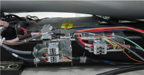
3.5 Power Pan
Power pan includes two parts (Simplified 120VAC Power Pan and Simplified HVDC Power Pan), located at the gantry base.
Figure 6. Power Pan
3.6 Gantry E-Stop
The gantry’s internal E-Stop performs the same function as the E-Stops mounted to the console and the gantry covers. See Figure 4.
4 Mechanical
4.1 Hazards
Inside the Gantry are several hazards that can cause personal injury from:
-
moving assemblies (rotational and tilt)
-
assembly weights (tube and covers)
-
chemicals (slip ring brush dust and oils {Tube, HV Tank and Tilt Drive Hydraulic Oil})
-
heat sources (tube)
4.2 Fastener Torque Specifications
To prevent assembly and part separations from the rotating assembly, all fasteners must be torqued to their proper specification, using a calibrated torque wrench. The torque specification for a fastener is specified in its associated replacement procedure. For further information on torque, including a conversion factor chart, refer to Torque Wrench Information.
4.3 Rotational Locking Pin
To prevent un-commanded or unintended motion of the rotating assembly, the rotational lock must be engaged anytime the rotating assembly is serviced.
Figure 7. Rotational Lock Assembly
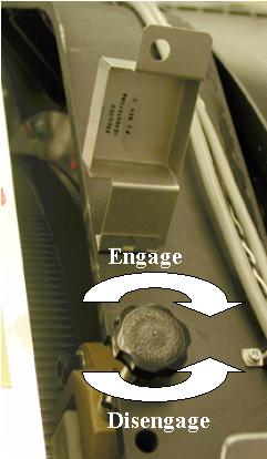
The rotational lock is located on the rear right side of the gantry, near the top. It is positioned directly across from the teeth in the rotational assembly. To operate the lock:
-
To Lock the gantry rotation, turn the handle clockwise until the teeth on the lock fully engage the teeth on the rotating assembly. If necessary, rock the rotating assembly slightly to align the teeth. Hand tighten until snug. Do not over-tighten. Visually verify that the teeth are engaged.
-
To unlock the gantry rotation, turn the handle counter-clockwise until the lock is fully retracted away from the gantry teeth and the handle can no longer be turned counter-clockwise.
4.4 Gantry Rotation to Start/Stop Rotor (Liquid Bearing Rotor Rule)
(For Performix Plus_LB Tube Only as below)
 |
|

 |
|
The Liquid Bearing tube rotor start/stop requires Gantry rotation. This is a new operation requirement for the LB Tube system. If operation does not need gantry rotation, ensure the Axial Drive is OFF when working in areas which may rotate.
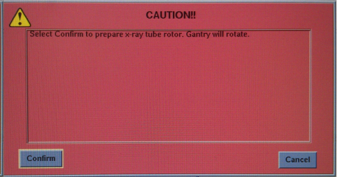
Be careful when performing replacement or troubleshooting processes with a Liquid Bearing tube as the gantry will need to rotate in some conditions. Pay attention when you see the above popup message. To allow tube rotation, make sure the path of the rotation is clear and all personnel are away from the gantry before selecting Confirm.
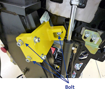
4.5 Tilt Function Lock-out Using the “Locking” Brackets
|
Spatial orientation defined in this section for is from the service perspective of an observer standing at the end of the patient table looking towards the Gantry Display board, through the gantry. This orientation defines a negative or minus gantry position which places the top of the gantry leaning away from the observer. Refer to System Safety Overview procedure section titled "Spatial Orientation While Servicing The System".
-
Position the gantry at zero degrees. Start on one side.
-
While holding the bracket in place (see Figure 8), secure the bracket to the stationary frame at locations 1 and 2. [Note: The two tilt brackets are identical.]
-
Next, secure the bracket to the pivoting frame at location 3.
-
Repeat these steps on the other side.
Figure 8. Tilt Locking Bracket (Right Side)
When the brackets and associated hardware are not in use, store them in the top compartment of the PDU.
4.6 X-Ray Tube Hoist
Whenever the x-ray tube is removed or installed, a tube hoist must be used. With the help of the tube hoist, one (1) person can change an x-ray tube.
4.7 Front and Rear Covers Dollies
|
The front and rear covers are designed to be safely removed by one (1) person, using the cover dollies supplied with your system. Because the weight of these covers could cause injury, these cover dollies must always be used. Both the installation manual and enclosure replacement procedures describe how to assemble and use cover dollies.