- Topic ID: id_15460171
- Version: 4.0
- Date: Jan 20, 2020 8:36:45 PM
Tilt Potentiometer Replacement (New)
Prerequisites
Overview
This procedure describes the steps to replace the Tilt Feedback Assembly.
1 Preparation
Procedure
- If the gantry is not at zero tilt, use the gantry control panel
to tilt the gantry close to zero tilt.note:
The tilt angle does not have to be exact. At zero tilt, there is more area for servicing the Tilt Pot Assembly.
- Move the table up to bore level and all the way back.
- Stop the rotor of X-ray tube in case of Liquid Bearing Tube before HVDC off. Refer to Liquid Bearing Tube Rotor stop procedure for details.
- Remove gantry right side cover and disable Axial drive, HVDC
and 120VAC service switches from the Service Switch Panel.
Refer to Replacement → Gantry → Enclosure → (Cover Removal Procedures).
- Remove the Gantry left side, top, front and rear covers.
- Turn on the gantry 120VAC service switch, and tilt the gantry all the way back to the tilt stop blocks using Tilt Service Switch with Tilt enable.
- Turn off the gantry 120VAC service switch.
2 Tilt Feedback Assembly Removal
Procedure
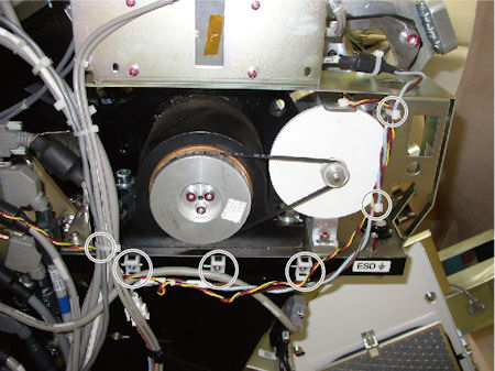
- Cut any tie-wraps holding the cable of the potentiometer to
the gantry frame.
Figure 1. Potentiometer Cable
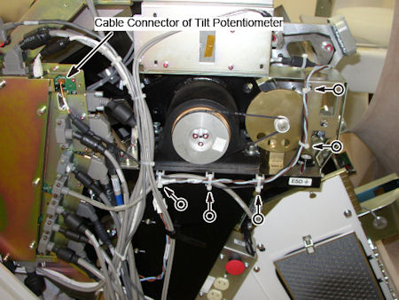
- Disconnect the cable connector of potentiometer from TGPG.
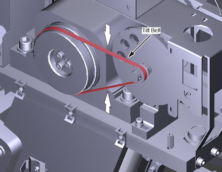
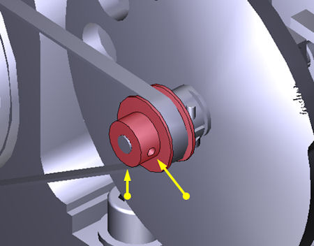
- Press the tilt belt in middle of the belt span, and make sure
of the degree of the tightened belt.note:
The new assembly will need to be adjusted to the same tension.
Figure 2. Tilt Belt
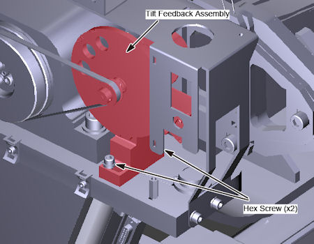
- Loosen two (2) hex screws holding the tilt feedback assembly to the gantry frame, to remove tension from the belt, and remove the belt.
- Remove the two (2) hex screws, and remove the tilt feedback
assembly from gantry.
Figure 3. Tilt Feedback Assembly Removal
3 Tilt Feedback Assembly Installation
Procedure
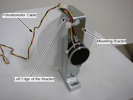
- Set the potentiometer cable along the left edge of the mounting
bracket, and fix the cable to the bracket using tie-wraps.
Figure 4. Tilt Feedback Assembly
- Put the tilt feedback assembly in place, and install the two hex screws loosely to hold the tilt feedback assembly in place.
- Position the belt on and around the tilt motor pulley and the small pulley of potentiometer.
- Move the tilt feedback assembly position to maintain a proper degree of tension (the same tension as before) for tilt belt.
- Tighten the two (2) hex screws to the following torque values.
- Connect the potentiometer cable to the TGPU.
- Using tie-wraps, secure the Tilt Pot cable to the gantry.
Figure 5. New Tilt Potentiometer Cable
- Using a 1.5 mm hex key, loosen the two hex screws on the front
of the tilt pot pulley (do NOT remove the screws). This allows the
tilt indicator disk to freely rotate for alignment.
Figure 6. Hex Screws on Tilt Pot Pulley
4 Tilt Alignment and Characterization
Procedure
- Clear all tools from the gantry.
- Using the Service Switches, turn ON 120 VAC, Service Mode and Tilt Enable.
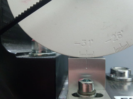
- Push down on the Tilt Service Switch to tilt the gantry backwards
(BWD) to the mechanical stops at -31° degrees.note:
The table position may inhibit tilt motion if it is in the interference matrix. Reposition the table to continue tilt.
- Rotate the Tilt Indicator Disk to -31°.
Figure 7. Alignment at –31°
- Using a 1.5 mm hex key, tighten the two hex screws on the front of the tilt pot pulley. Refer to Step 8.
- Perform Tilt Characterization. Check for possible interference.
- Go to Service Desktop — Calibration — Mechanical Calibration — Characterize Tilt
- Follow on screen instructions.note:
When not in the Service Mode, normal tilt button function provides 0.5 degrees per button press, which is not enough resolution for proper characterization. On the Service Panel, set Service Mode (S4) switch ON to enable a fine tune adjustment of the tilt angle. Remember to turn S4 OFF when done.
note:Prior to Tilt Characterization, the tilt reading maybe greater than the 30 degrees limit. This will inhibit the tilt function from the gantry control panel. If this occurs, use the Tilt (S10) Service Switch to tilt the gantry for characterization.
- Tilt the gantry back to home position and confirm the Tilt Indicator Disk lines up at zero degrees.
- Install Gantry Front and Rear cover.
- At Service Switch Panel, turn OFF Tilt Enable and Service Mode. Turn ON Axial Enable and HVDC.
- Re-install Left and Right Side covers.
5 Finalization
Procedure
- Run the System scanning test from the Functional Checks procedure list.
- Run the Quality Assurance test from the Functional Checks procedure list.
- Save System State.