- Topic ID: id_17423037
- Version: 4.0
- Date: Jan 20, 2020 8:32:00 PM
Thermistor Assembly Replacement
Prerequisites
Overview
This procedure defines the necessary steps to Remove and Install the Thermistor Assembly.
1 Preparation
Procedure
- Move table to home position, fully out and down.
- Remove right side gantry cover.
Refer to Parts Replacement → Gantry → Enclosure → (Cover Removal Procedure).
- Stop the rotor of X-ray tube in case of Liquid Bearing Tube before HVDC off. Refer to Liquid Bearing Tube Rotor stop procedure for details.
- Turn OFF the Axial Drive and HVDC switches on the gantry’s Service Switch Panel.
- Position the detector at 12 o'clock and lock gantry rotation.
- Turn OFF the 120 VAC switch on the gantry’s Service Switch Panel.
- Remove the gantry left side cover, top covers and front cover.
2 Replacement Procedure (Low Channel Side)
2.1 Removal Procedure
Procedure
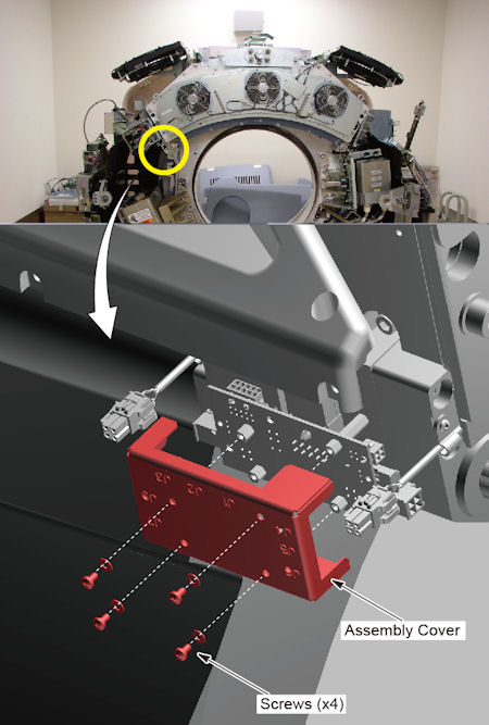
- Remove 4 screws, and remove the assembly cover.
Figure 1. Thermistor Assembly Cover Removal
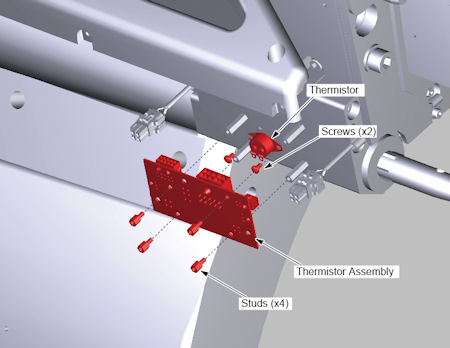
- Disconnect all cable connector from the thermistor assembly.
- Remove 4 studs and 2 screws, and remove the thermistor assembly.
Figure 2. Thermistor Assembly Removal
2.2 Installation Procedure
Procedure
- Install the new thermistor assembly into place.
- Fix the thermistor assembly using the 2 screws and 4 studs.
- Reconnect all cable connector.
- Install the assembly cover using the 4 screws
3 Replacement Procedure (High Channel Side)
3.1 Removal Procedure
Procedure
- Engage gantry rotational lock.
- Remove HV cables to HEMIT tank and remove HEMIT Tank assembly to access screws for thermistor assembly cover. Refer to HEMIT Tank Replacement.
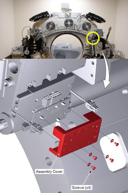
- Remove 4 screws, and remove the assembly cover.
Figure 3. Thermistor Assembly Cover Removal
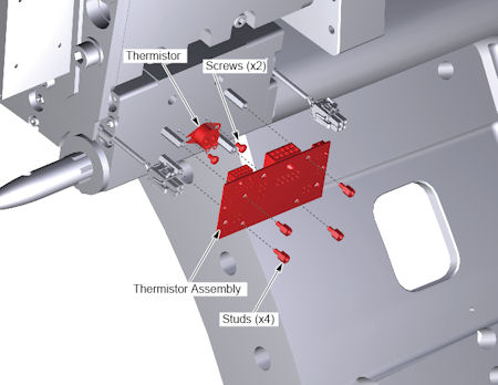
- Disconnect all cable connector from the thermistor assembly.
- Remove 4 studs and 2 screws, and remove the thermistor assembly.
Figure 4. Thermistor Assembly Removal
3.2 Installation Procedure
Procedure
- Install the new thermistor assembly into place.
- Fix the thermistor assembly using the 2 screws and 4 studs.
- Install the assembly cover using the 4 screws
- Reconnect all cable connector.
- Install HEMIT tank and connect HV cables. Refer to HEMIT Tank Replacement.
- Restore gantry rotational lock.
4 Gantry Reassembly
Procedure
- Make sure the Axial Drive, HVDC and 120 VAC switches on the gantry’s Service Switch Panel are OFF.
- Release the gantry rotational lock and install gantry covers,
all except the right side cover.
Refer to Replacement → Gantry → Enclosure → (Cover Removal Procedures).
- Turn on the 120 VAC, HVDC and Axial drive service switches.
- Install gantry right side cover.
5 Finalization
No finalization steps.