- Topic ID: id_17422982
- Version: 2.0
- Date: Mar 6, 2020 10:01:32 PM
TGPG Power Supply Replacement
Prerequisites
Overview
This procedure defines the steps necessary to replace the TGPG power supply behind the TGPG board assembly.
Procedure
- Remove gantry right side cover.
Refer to
- Turn OFF the Axial Drive, HVDC and 120 VAC switches on the gantry’s Service Switch Panel.
- Remove the gantry left side cover, top covers and front cover.
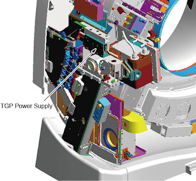
- The power supply is located above the tilt potentiometer assembly
(see Figure 1.)
Figure 1. Power Supply Location
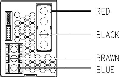
- Disconnect the power leads from the power supply.
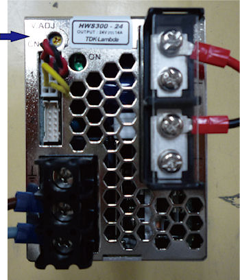
Figure 2. Power Leads of the Power Supply
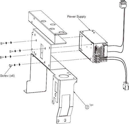
- Remove the 4 screws that hold the power supply and bracket (see
)Figure 3.
Figure 3. Power Supply Screw Locations
- Remove the defective power supply.
- Install the new power supply to the bracket using the 4 screws removed from the old power supply.
- Reconnect the power leads to the power supply (see Figure 2).
Finalization
- Turn ON the gantry 120 VAC service switch, press the e-stop reset button on the lower right of the service switch panel and power up the console.
- Check and Adjust the power supply voltages as follows. Reference Figure 4 for test point
location and Figure 5 for adjustment screw location.
- Using a voltmeter check the voltage between TP16 and TP17 on the TGPG. Adjust screw to have 24V +/- 0.2V.
- -
Figure 4. TGPG Test Point location
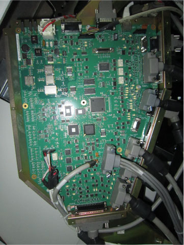
Figure 5. Adjustment screws (Top of supply)
- Install the gantry rear cover, top covers and left side cover.
Refer to
- Enable 120 VAC HVDC and Axial Drive service switches from the service switch panel. Press the E-stop reset enable button on the lower right corner of the service switch panel.
- Install the gantry right side cover.
- Perform a System Scanning Test from the Functional Checks menu of the service manual to ensure system operation.