- Topic ID: id_17423013
- Version: 5.0
- Date: Jan 20, 2020 8:35:22 PM
Slip Ring Adjustments
Prerequisites
Overview
This procedure defines the methods to adjust the receiver and check transmission statistics to verify proper operation.
1 Slip Ring Receiver Adjustment Procedure
This document describes the steps necessary to properly adjust the position of the Receiver antenna above the emitter traces on the rotating slip ring. Accurate placement of the antenna is important to achieve the optimal data transfer performance and to avoid contact between the ring and the stationary antenna. The optimal position of the antenna above the emitter traces on the ring is 1.41 mm height (.060 inches), and centered. Under normal circumstances, the position of the antenna should never need adjustment. Only adjust if there are indications of interference. Under no circumstances should the antenna be allowed to contact the rotating components.
Procedure
- Remove the gantry right side cover.
- Stop the rotor of X-ray tube in case of Liquid Bearing Tube before HVDC off. Refer to Liquid Bearing Tube Rotor stop procedure for details.
 danger
- Disable gantry Axial drive, HVDC and 120 VAC service switches from the service switch panel.
- Perform appropriate LOTO procedures to lock out power to the gantry.
- Remove mylar scan window and gantry left side, top and rear
covers. Connect the E-stop cable removed from the back cover to the
gantry terminator in preparation for later steps.
Refer to
- Remove the top slip ring cover to access the receiver.
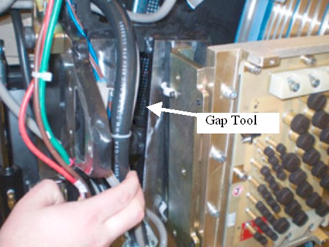
- Pull out the gap tool from the gantry frame storage location.
Figure 1. Gap Tool Location
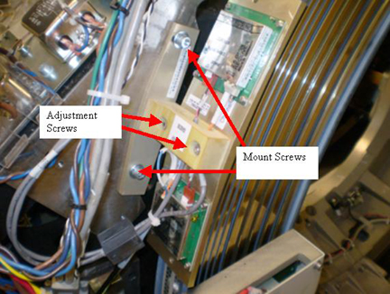
- Loosen the Mount screws (5 mm hex wrench) for the receiver assembly
to adjust for antenna to receiver gap.
Figure 2. Receivers
- The antenna should now be loose above the emitter. Insert the adjustment tool between the receivers and the antenna on the ring. The tool should fit snugly. The desired result is to space the antenna above the emitter, at a height of 1.41 mm (.060 inches) above the emitter with the gap tool as the gage for this spacing.
- Press slightly on the top of the antenna as the adjustment screws are tightened.
- Torque the M6 mount screws to:
- Carefully slide the adjustment tool from between the antenna and the emitter.
- Loosen the adjustment screws (4 mm hex wrench), reference Figure 2, and adjust
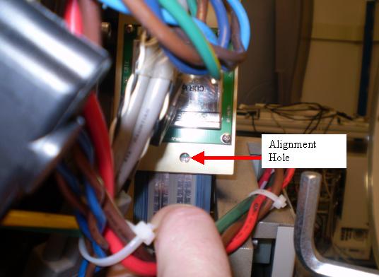
the RF Receiver assembly such that the top and bottom alignment holes
line up with the center line of the RF antennas on the slip ring.
Figure 3. Receiver Alignment Top hole
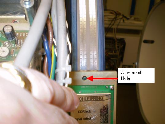
Figure 4. Receiver Alignment Top hole
- While holding the position of the antenna, tighten the alignment
screws and torque to.
- notice
- Inspect the air-gap between the antenna and the ring by rotating
the gantry in small increments of about 3 feet (1 meter). Look for
clearances between the emitter and the antenna. While rotating the
ring, check that the emitter trace is aligned with the antenna. During
rotation, no parts of the antenna should contact the emitter surface.note: It will be hard to rotate the ring without power applied but this step intentionally leaves power off due to the exposed slip rings.
-
The stationary and rotating components must never touch, even with the gantry tilted.
-
The run-out of the platter slip ring traces should not exceed 0.83 mm axially, and 0.81 mm radially. If the ring appears to shift with respect to the receivers, use the Slip Ring Platter Replacement procedure to check ring run out.
-
Especially check clearances near the slip ring antenna emitter solder and PCB connections.
-
- Install the top slip ring cover before restoring any power.
- Restore power to the system by removing LOTO.
- danger
- danger
- Enable gantry 120 VAC, HVDC and Axial Drive to prepare for testing slip ring transmission path.
 |
 |
|
2 Slip Ring DIP stats
Procedure
- Verify proper operation by running verification scans. Verification
procedure should consist of:
- Run 5 stationary and 5 rotational scans with x-ray. The technique is not important. It is important to exit the exam, because this triggers the “DIP Stats” update.
- From the Common Service Desktop, Diagnostics tab, select RTS viewer.
- Choose the DIP selection and view each scans DIP stats. There should be no FEC Failures or Sync Errors.
Exam Number: 00263,ENDEXAM
Date: Fri Mar 21 02:05:33 2008
Offset Data Bytes 0 Bytes
Image Data Bytes 0 Bytes
Number of Das Data Buffer Overruns 0 Overruns
abort 0 Aborts
FEC Attempts 0 Bytes
Bit Error Rate 0.0 Rate
FEC Failures 0 Failures
Num of SYNC Errors 0 Errors
View interpolations 0 Interpolations
- danger
- If there are transmission issues disable Axial Drive and HVDC
from the service switch panel, then check the power to the transmitter
and receiver and alignments.
-
Transmitter power supply measurements
-
The Transmitter Power comes from the rotating 48V power supply by way of the ORP. A 48V feed goes to the ORP and then to the transmitter.
-
Measure the DC voltage on the wires at the ORP connector leading to the Transmitter. The specification is +48 volts DC ± 5.0 volts.
-
-
Receiver power supply measurements
-
Locate the Receiver Power supply next to the GFI breaker behind the Service Switch Panel.
-
Measure the DC voltage on the wires leading to the Receiver. The specification is +15 volts DC, ± 2.0 volts. Use indicator LEDs to ensure proper operation.
-
-
|
3 Finalization
Procedure
- Turn off Axial Drive, HVDC, and 120 VAC service switches from the service switch panel.
- Replace the gantry covers (except right side cover). Re-install
the mylar window.
Refer to
- Turn on 120 VAC, Axial Drive and HVDC service switches from the service switch panel. Enable table drives and install the gantry right side cover.
- Perform System scanning test from the Functional
Checks section to verify scanner operation.