- Topic ID: id_17423476
- Version: 4.0
- Date: Feb 22, 2022 12:50:34 AM
Power Supply Replacement
Prerequisites
Procedure
- notice
- Move the cradle to the OUT mechanical limit position by hand.
- Raise the Table to its highest position.
- Remove power from Table by turning off “120VAC”, “Axial Drive” and “HVDC” switches on the service switch panel.
- Remove the following cover from the Table:
-
Rear Bottom Cover (Refer to Table Covers Removal)
-
- Remove 4 screws, and slide the power driver support toward the
Gantry.
Figure 1. Power Driver Support
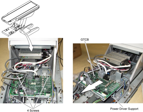
- Disconnect all cable connectors from the GTCB Assembly.
- Remove 8 screws, and remove the GTCB Assembly from the power driver support.
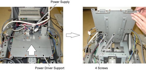
- Pop free and remove the plastic guard from the front of the power supply terminals.
- Mark and remove the wires from the terminal.
- Remove the Power Supply by unscrewing its four screws.
Figure 2. Power Supply Removal
- Install the new Power Supply by referring toStep 10 through Step 6.
- Check that the voltage is within +24V±1.2V. If not, adjust it by turning the potentiometer of the Power Supply.
- Restore the Table to original configuration.
 |
Finalization
No finalization steps.