- Topic ID: id_17423459
- Version: 4.0
- Date: Aug 10, 2021 9:57:01 PM
HP Host Computer Z820 FDIP Card Replacement
Prerequisites
Overview
This procedure shall be followed when replacing the FDIP Card in a Z820 computer.
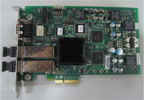
Figure 1. FDIP Card
Procedure
- Select one of the following methods to Power OFF the Operator
Console:
- If Applications are up, click on the Shut Down button and select Shutdown.
The Operator Console monitor will display a 'Power Down' message when it is acceptable to power OFF the Operator Console.
- If Applications are down, open a Unix Shell. Type: halt.
- If Applications are up, click on the Shut Down button and select Shutdown.
- Power OFF the console at the front panel switch when ‘System Halted’ message is displayed.
- Remove the left side and rear covers from the console.
Refer to
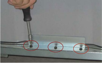
- Remove bracket by unscrew three screws as following illustration.
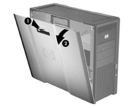
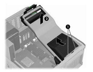
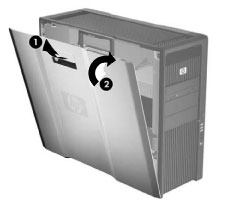
- Pull up on the handle (1) and rotate the side access panel off
the chassis (2) as shown in the following illustration.
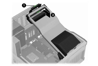
- Remove the expansion card support by lifting firmly on the handle
at the green touch point (1), and then rotating the support upward
(2) as shown in the following illustration.
- Disengage the expansion card support tabs from the rear chassis
slots (1), and then lift the support from the chassis (2) as shown
in the following illustration.
- Remove the following components from the host computer (Z820):
-
Side Access Panel
-
Expansion Card Support
-
- Replace the existing z820 FDIP card with new one.
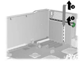
- Raise the rear retention clamp by lifting the metal bar or the
green lever as shown in the following illustration (1). Remove the
PCI slot cover by pulling it up, out of the chassis (2).
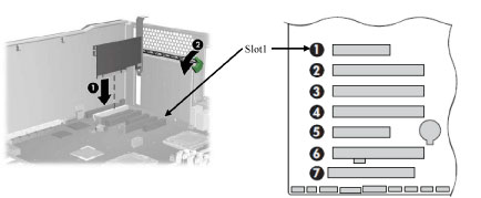
- Align the PCI card keyway with the slot key, and then firmly
seat the card in the slot 1 as shown in the following illustration
(1). Close the expansion card retention clamp by rotating it downward
(2). The retention clamp is secured by the expansion card support.
NOTE: The FDIP card should be installed on slot 1
- Raise the rear retention clamp by lifting the metal bar or the
green lever as shown in the following illustration (1). Remove the
PCI slot cover by pulling it up, out of the chassis (2).
- Insert the expansion card support tabs in the rear chassis slot
(1), and then lower the support until it click into place in the chassis
(2) as shown in the following illustration.
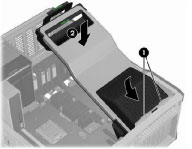
- Align the bottom groove of the side access panel with the bottom
edge of the chassis. Rotate the side access panel toward the chassis
and press firmly until the latch engages.
- Reinstall all removed components, and reconnect any cables that have been disconnected.
Finalization
- Refer to System Scanning Test to confirm proper operation.
- Reinstall the console covers.