- Topic ID: id_17423043
- Version: 3.0
- Date: Apr 22, 2019 12:56:26 AM
Gantry Heater Replacement
Prerequisites
Overview
This procedure defines the steps necessary to replace the gantry heater/blower assembly.
Procedure
- Move table to its lowest elevation.
- Remove gantry right side cover.
Refer to
- Stop the rotor of X-ray tube in case of Liquid Bearing Tube before HVDC off. Refer to Liquid Bearing Tube Rotor stop procedure for details.
- Turn OFF the Axial Drive and HVDC switches on the gantry’s Service Switch Panel.
- Rotate the gantry by hand to gain clear access to the heater assembly. Position the tube at approximately 9 o'clock which will have the weight stack above the detector at the 3 o'clock position behind the service switch panel.
- Turn OFF the 120 VAC switch on the gantry’s Service Switch Panel.
 danger
- Perform all required LOTO activities to remove all power to the gantry.
- Remove the gantry left side cover, top covers and front cover.
- Remove the gantry tilting assembly bottom cover.
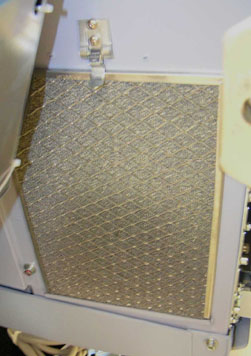
- The heater has an air intake filter on the left side. See Figure 1.
Figure 1. Air Intake Filter
- Remove the 3 screws in the front by the latch using a 5 mm hex
wrench. See Figure 2.
Cj M40 uses different blower, but screw location is same.
Figure 2. Heater Screws (Cj Phase 2.5)
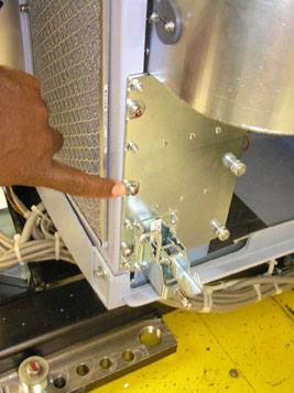
Figure 3. Gantry Heater Mounting Screws
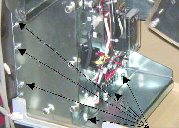
- Remove the 3 screws on the inside plate that holds the heater to the plate using a 5 mm hex wrench.
- Slide the heater forward and carefully remove all connecting cables.
- Carefully remove the heater assembly from the gantry.
- Install the new heater assembly by reversing the above steps. Install all hardware and cables.
- Torque the Heater assembly mounting screws to:
- Install the gantry tilting assembly base cover.
- Install the gantry front cover, top covers and left side cover.
Refer to
- Remove LOTO and restore power to system.
- Enable 120 VAC HVDC and Axial Drive service switches from the service switch panel. Press the table drives enable button on the lower right corner of the service switch panel.
- Install the gantry right side cover.
Finalization
- Perform a System Scanning Test from the Functional Checks menu of the service manual to ensure system operation.