- Topic ID: task_e2c_2v4_1jb
- Version: 4.0
- Date: Dec 22, 2021 11:23:11 PM
GT Top Side Cover Bracket Replacement
Prerequisites
Overview
This Procedure defines how to replace the GT Top Side Cover bracket.
The following FRU kits were prepared for field upgrade of the brackets.
Please note that both frame side and cover side brackets need to be replaced at once.
Figure 1. Table Top Cover BRKT List
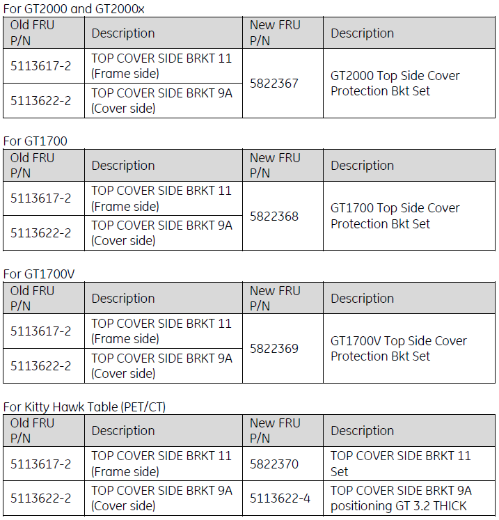
This procedure includes GT2000 & GT2000x, GT1700V, GT1700, and KH tables. After completed Preparation procedure, please find out appropriate table type from Table 3.
1 Preparation
Procedure
- Raise the Table to maximum height.
- Move the Cradle and IMS to OUT limit position.
- Remove power from Table by turning off 120VAC, Axial Drive and HVDC switches on Service Switch Panel.
2 GT2000 & GT2000x Table
Procedure
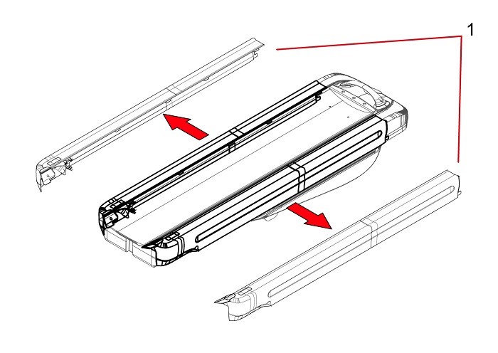
- Remove the Table Top Cover (Right/Left).
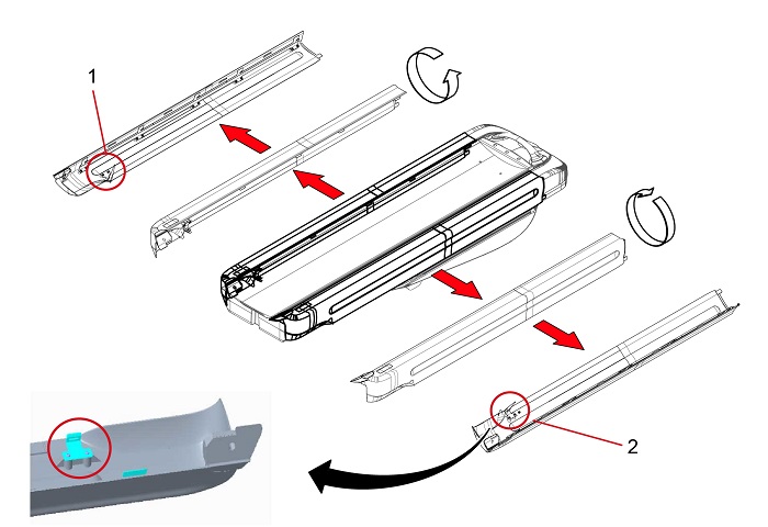
Figure 2. Table Top Cover (Right/Left)
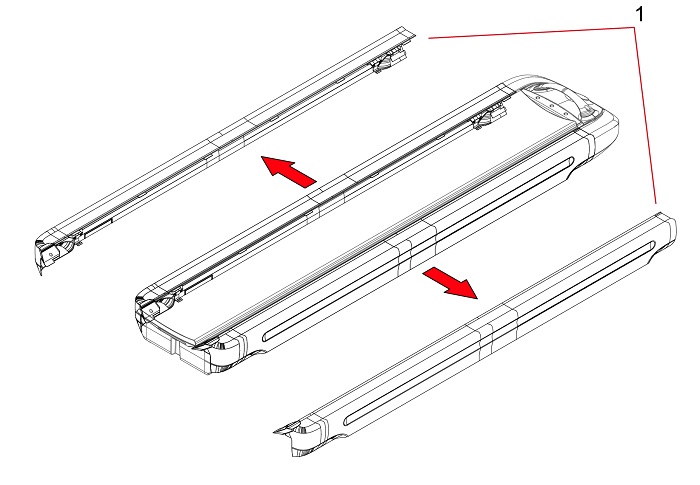
1 Top Cover (Right/Left) - Replace the top cover side brackets.
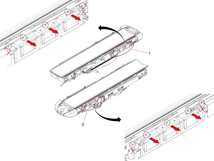
- Remove four (4) mounting brackets (item 1 through 4 in Figure 3).
Figure 3. Remove Mounting Brackets
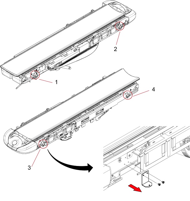
1 - 4 Four (4) Mounting Brackets - Set the new brackets in appropriate position.
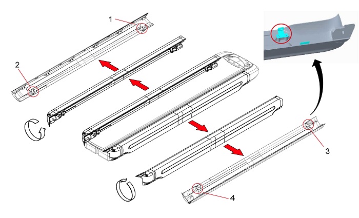
Figure 4. Top Side Cover Brackets
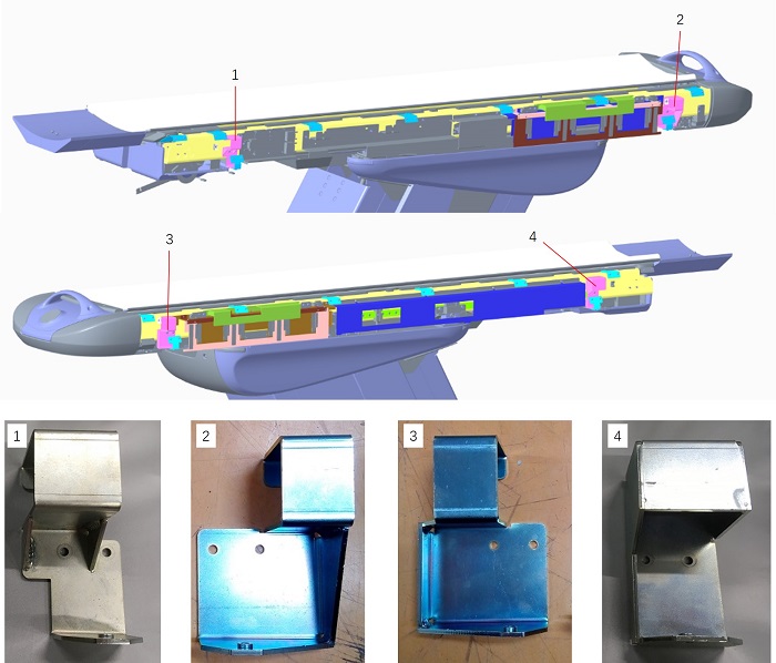
1 5822366: Top Cover Side Bracket LF 2 5814161: Top Cover Side Bracket LR 3 5814162: Top Cover Side Bracket RR 4 5814163: Top Cover Side Bracket RF note:Routing the cable as shown in Figure 4. Do not put the cable between the table and the brackets.
Cut tie-wraps as necessary. If tie-wraps are cut, secure the cables by new tie-wraps after the Brackets are installed.
Figure 4. Routing the Cables
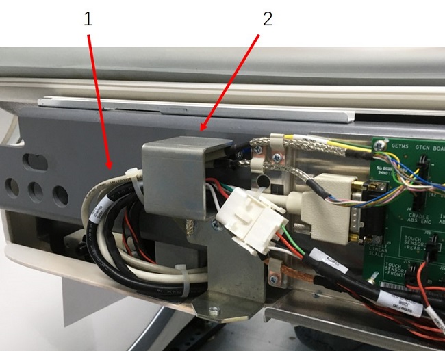
1 Cables 2 Bracket - Secure each top side cover bracket by two (2) screws.
- Remove four (4) mounting brackets (item 1 through 4 in Figure 3).
- Install Protect brackets
- Remove three (3) screws on each touch sensor.note:
Each touch sensor is secured by five (5) screws, so remove center three (3) screws as shown in Figure 6. Do not remove two (2) screws on right and left end of the touch sensor.
Figure 6. Remove Screws on Touch Sensor
1 5127469-3: Touch Seonsor (Left) 2 5127470-3: Touch Sensor (Right) - Set new protect brackets in right and left side of the table.
Figure 7. Protect Brackets Installation
1 5814165: Protect Bracket (Left) 2 5814167: Protect Bracket (Right) - Secure each protect bracket by three (3) screws.
- Remove three (3) screws on each touch sensor.
- Replace top cover side bracket 9A .
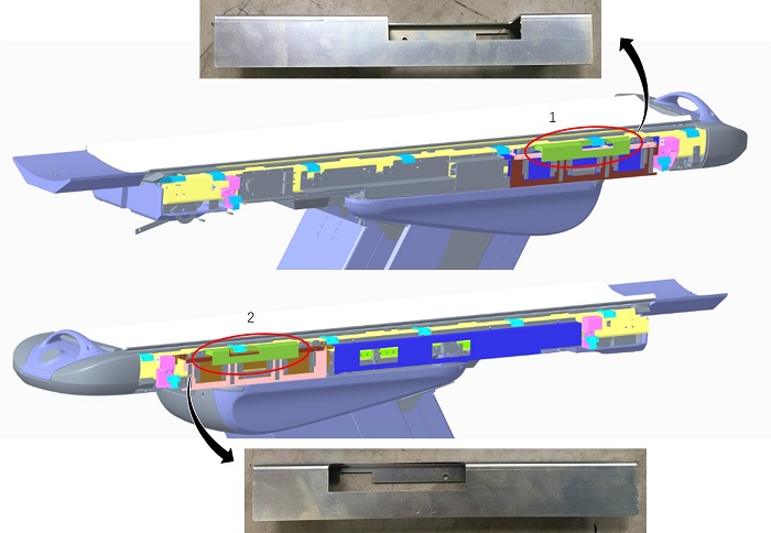
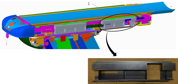
- Remove four (4) mounting brackets (item 1 through 4 in Figure 8) by removing eight (8) screws.
Figure 8. Replace Side Brackets
1 - 4 Mounting Brackets - Set new brackets (5113622-4) on both top covers, same as Figure 8.note:
Set the Brackets at the top of screw hole.
Figure 9. Screw Hole in the Bracket
1 Screw Holes - Secure each top side cover bracket by two (2) screws.
- Remove four (4) mounting brackets (item 1 through 4 in Figure 8) by removing eight (8) screws.
3 GT1700V Table
Procedure
- Remove the Table Top Cover (Right/Left).
Figure 10. Table Top Cover (Right/Left)
1 Top Cover (Right/Left) - Replace top cover side bracket LF
- Remove the mounting bracket by removing two (2) screws, as shown in Figure 11.
Figure 11. Remove Mounting Bracket LF
1 Mounting Bracket - Set a new bracket.
Figure 12. Side Bracket LF
1 5822366: Top Cover Side Bracket LF - Secure the top cover side bracket by two (2) screws.
- Remove the mounting bracket by removing two (2) screws, as shown in Figure 11.
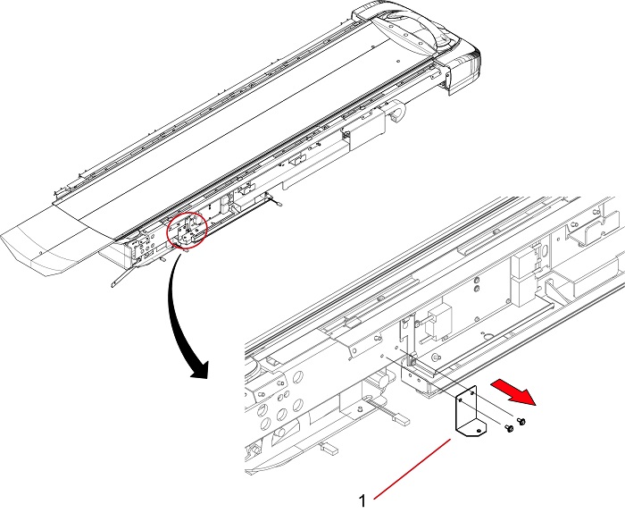
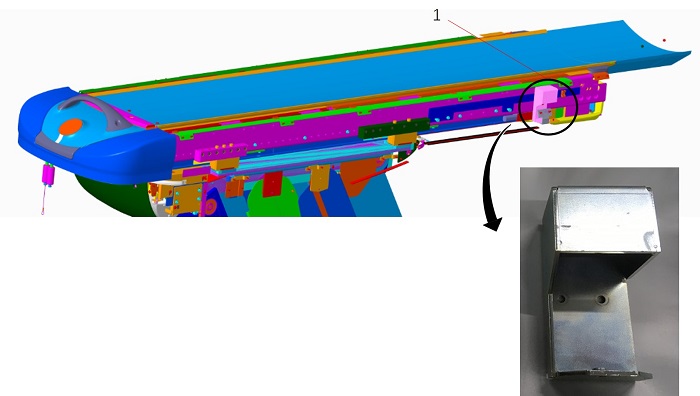
- Replace top side cover support.
- Remove the mounting bracket by removing three (3) screws, as shown in Figure 13.
Figure 13. Remove Mounting Bracket
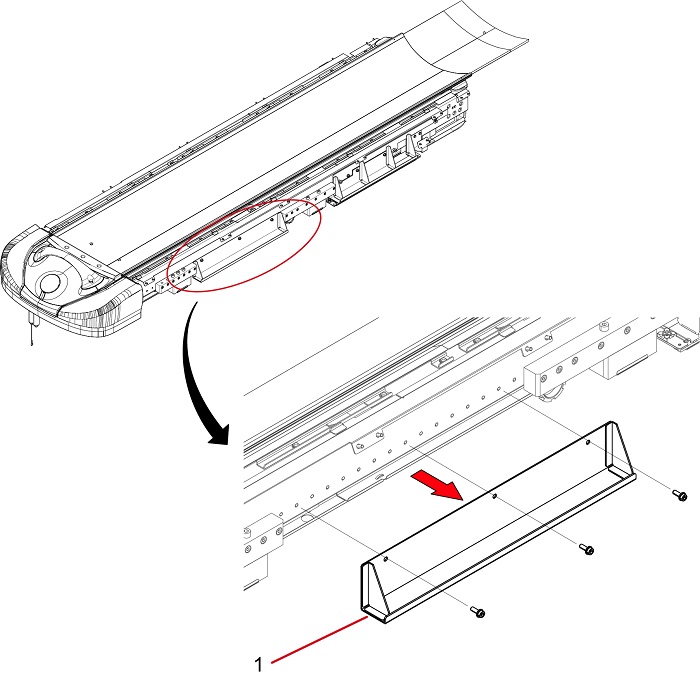
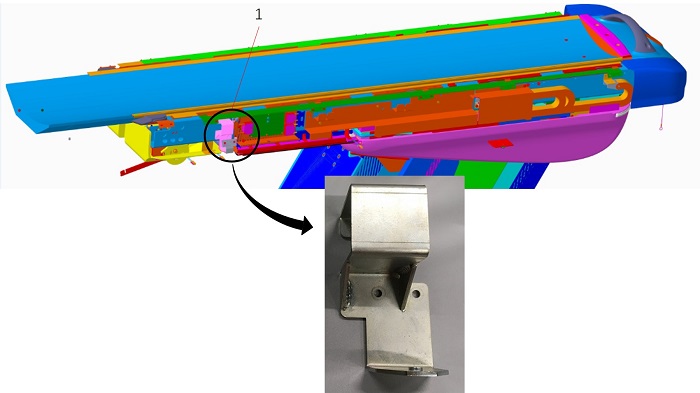
1 Mounting Bracket - Set a new side cover support.
Figure 14. Top Side Cover Support
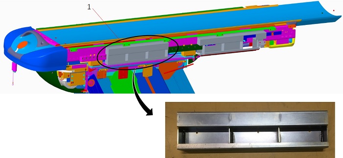
1 5331271-2: Top Side Cover Support - Secure the top side cover support by three (3) screws.
- Remove the mounting bracket by removing three (3) screws, as shown in Figure 13.
- Replace front SW Bracket.
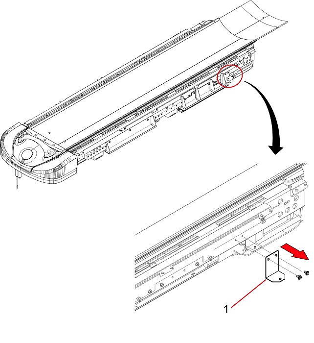
- Remove the mounting bracket by removing four (4) screws, as shown in Figure 15.
Figure 15. Remove Mounting Bracket
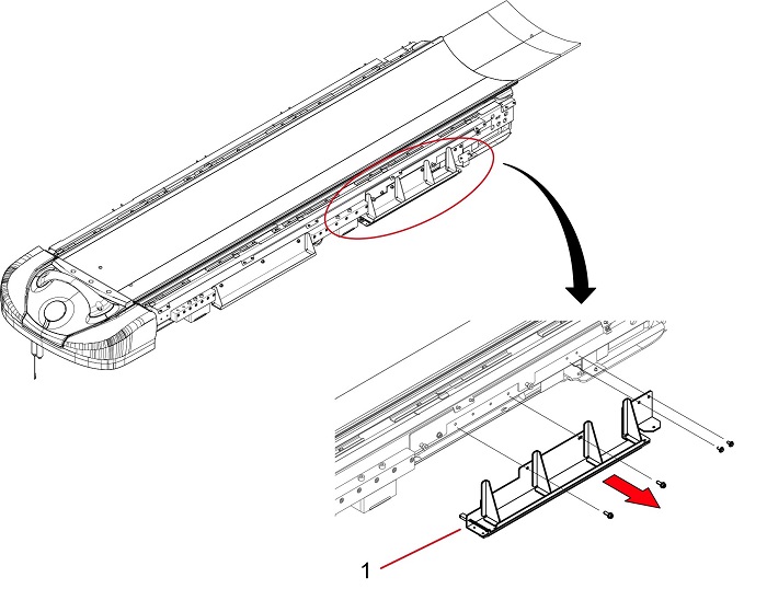
1 Mounting Bracket - Install the tape switch to a new front SW bracket as follows.
- Install a new tape switch (5330654-4) to the SW bracket.
- If a new tape switch (5330654-4) is not available, remove the tape switch from the mounting bracket carefully. Then, install the removed tape switch to the SW bracket.
Figure 16. Tape Switch Location
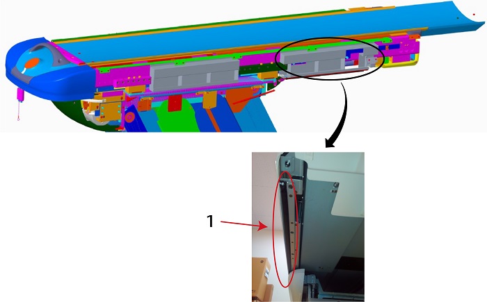
1 5330654-4: Tape Switch Front - Set the SW bracket.
Figure 17. Front SW Bracket
1 5326823-2: Front SW Bracket - Secure the SW bracket by four (4) screws.
- Remove the mounting bracket by removing four (4) screws, as shown in Figure 15.
- Replace top cover side bracket 9A.
- Remove two (2) mounting brackets (item 1 and 2 in Figure 18) by removing four (4) screws.
Figure 18. Replace Side Brackets
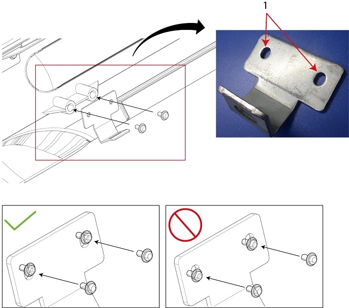
1 - 2 Mounting Brackets note:Set the Brackets at the top of screw hole.
Figure 19. Screw Hole in the Bracket
1 Screw Holes - Set new brackets (5113622-4) on both top covers, same as Figure 18.
- Secure each top cover side bracket by two (2) screws.
- Remove two (2) mounting brackets (item 1 and 2 in Figure 18) by removing four (4) screws.
4 GT1700 Table
Procedure
- Remove the Table Top Cover (Right/Left).
Figure 20. Table Top Cover (Right/Left)
1 Top Cover (Right/Left) - Replace top cover side bracket LF.
- Remove the mounting bracket by removing two (2) screws, as shown in Figure 21.
Figure 21. Remove Mounting Bracket LF
1 Mounting Bracket - Set a new bracket.
Figure 22. Side Bracket LF
1 5822366 : Top Cover Side Bracket LF - Secure the bracket by two (2) screw.
- Remove the mounting bracket by removing two (2) screws, as shown in Figure 21.
- Replace top cover side bracket RF.
- Remove mounting bracket by removing two (2) screws, as shown in Figure 23.
Figure 23. Remove Mounting Bracket RF
1 Mounting Bracket - Set a new bracket.
Figure 24. Side Bracket RF
1 5814163: Top Cover Side Bracket RF - Secure the bracket by two (2) screw.
- Remove mounting bracket by removing two (2) screws, as shown in Figure 23.
- Replace top cover side bracket 9A.
- Remove two (2) mounting brackets (item 1 and 2 in Figure 25) by removing four (4) screws.
Figure 25. Replace Side Brackets
1 - 2 Mounting Brackets note:Set the Brackets at the top of screw hole.
Figure 26. Screw Holes in the Bracket
1 Screw Holes - Set new brackets (5113622-4) on both top covers, same as Figure 25.
- Secure each top cover side bracket by two (2) screws.
- Remove two (2) mounting brackets (item 1 and 2 in Figure 25) by removing four (4) screws.
For GT1700, figures are reference only.
5 KH Table
Procedure
- Remove the Table Top Cover (Right/Left).
Figure 27. Table Top Cover (Right/Left)
1 Top Cover (Right/Left) - Replace top cover side brackets.
- Remove four (4) mounting brackets (item 1 through 4 in Figure 28).
Figure 28. Mounting Brackets on Side
1 - 4 Four (4) Mounting Brackets - Set the new brackets in appropriate position.
Figure 29. Top Side Cover Brackets
1 5822366: Top Cover Side Bracket LF 2 5814161: Top Cover Side Bracket LR 3 5814162: Top Cover Side Bracket RR 4 5814163: Top Cover Side Bracket RF - Secure each top side cover bracket by two (2) screws.
- Remove four (4) mounting brackets (item 1 through 4 in Figure 28).
- Replace top cover side bracket 9A.
- Remove four (4) mounting brackets (item 1 through 4 in Figure 30) by removing eight (8) screws.
Figure 30. Replace Side Brackets
1 - 4 Four (4) Mounting Brackets note:Set the Brackets at the top of screw hole.
Figure 31. Screw Holes in the Bracket
1 Screw Holes - Set new brackets (5113622-4) on both top covers, same as Figure 30.
- Secure each top cover side brackets by two (2) screws.
- Remove four (4) mounting brackets (item 1 through 4 in Figure 30) by removing eight (8) screws.
For KH Table, figures are referecnce only.
6 Finalization
Procedure
- Re-install the table covers.
- Power up the Table from the service Switch Panel in Gantry.
- Move the cradle In/Out completely 10 cycles, and verify that the cradle movement is operating normally.