- Topic ID: id_17423052
- Version: 4.0
- Date: Apr 22, 2019 12:55:45 AM
Dual Channel Fiber Rx Replacement
Prerequisites
Overview
This procedure defines the steps necessary to replace the dual channel fiber receiver replacement.
1 Prepare Gantry for Receiver Replacement
Procedure
- Remove the gantry right side cover.
- Stop the rotor of X-ray tube in case of Liquid Bearing Tube before HVDC off. Refer to Liquid Bearing Tube Rotor stop procedure for details.
- Turn OFF all 3 service switches (Axial Drive, HVDC, 120VAC) on the Service Switch Panel.
- Shut down system software and completely shut down system power. Use LOTO to remove power from gantry.
- Remove Gantry left side and top covers, and slide out the rear
cover.
Refer to
- Remove the top Slip Ring safety cover.
2 Replace the Receiver
Procedure
- The receivers are located above the Slip Ring Brush Block. Remove the top slip ring cover to gain access to the receivers.
- Remove the power and fiber cables from the receivers.
Figure 1. Slip Ring Receivers
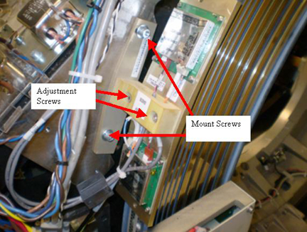
- Remove the two (2) M6 hex head screws (5 mm hex wrench).
- Remove the receiver assembly and put the new assembly in place.note:
Fiber cables are keyed and should be replaced in the same receiver as removed.
- Install the two (2) M6 hex head screws (5 mm hex wrench), and two (2) cables but do not tighten screws.
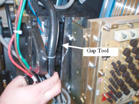
- Locate the Receiver gap tool and place it between slip ring
antenna and receivers. The tool defines the necessary gap between
receivers and slip ring.
Figure 2. Gap Tool Location
- Tighten M6 mount screws and torque to:
- Remove alignment tool and put it back in storage location on gantry.
- Loosen M5 adjustment screws (4 mm hex wrench) to allow adjustment of receivers to slip ring antenna. Reference Figure 1.
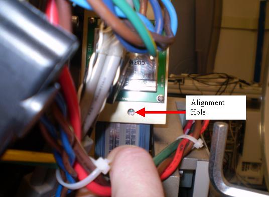
- Align centerline of the receiver to centerline of antenna through
small alignment hole for both top and bottom receivers as shown in Figure 3 and Figure 4.
Figure 3. Top Alignment Hole
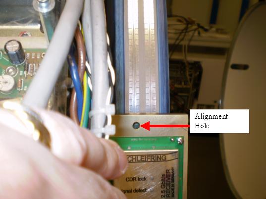
Figure 4. Bottom Alignment Hole
- Torque M5 Adjustment screws to:
3 Power-Up
Procedure
- Remove the A1 Lock-Out Tag-Out and power up the console.
- Turn on the Gantry 120 VAC service switch and slowly rotate the gantry by hand while watching the gap between the receivers and antenna. Make sure the antenna never touches the two receivers.
- Turn off the gantry 120 VAC service switch and install the top slip ring cover.
- Turn on the 120 VAC, HVDC and Axial drive service switches and enable Table drives.
- Perform a System Scanning Test from the Functional Checks menu of the service manual to ensure proper data transmission.
- Check the RTS Dip stats for the scan just run and make sure there are no errors shown. If errors are shown, recheck alignments and cable connections.
- Turn off the Axial Drive, HVDC, and 120VAC service switches.
- Install the gantry rear cover, top covers and left side cover.
Refer to
- Turn on the 120VAC, HVDC and Axial drive service switches and enable Table drives.
- Install the gantry right side cover.
4 Finalization
Procedure
- No further finalization required since checks have already been done above.