- Topic ID: id_17423030
- Version: 5.0
- Date: Jun 4, 2020 8:07:20 PM
Detector Carbon Window Replacement - Merc40
Prerequisites
Overview
This procedure defines the necessary steps to Remove and Install the Detector Carbon Window.
Carbon window replacement kit includes wide and slim type carbon windows, so identification of appropriate window is required.
- Check Label on High channel side end block as shown in Figure 1.
Figure 1. Label on High Channel Side End Block
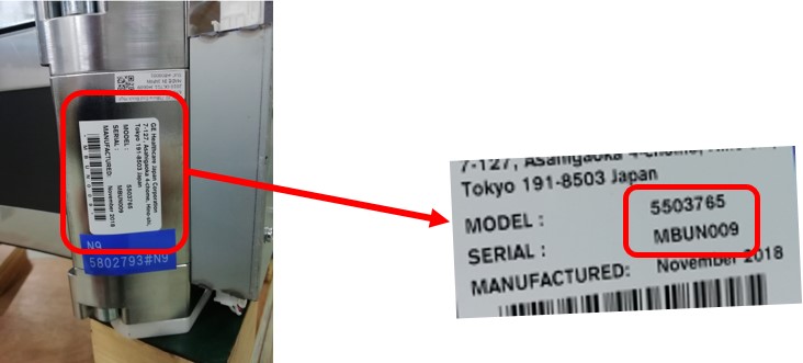
- Verify MBU P/N in Table 6 to identify rail type.
- Once identify rail type, refer to Carbon Window P/N in Table 6 and choose appropriate window for replacement.
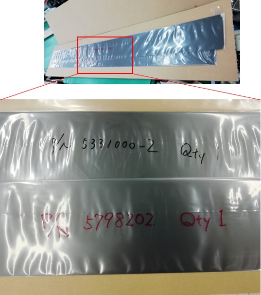
Carbon windows are packed between card boards, and P/N is indicated in package as shown in Figure 2.
Figure 2. Carbon Window Part Number on Package
- The FRU Kit includes three pieces of long aluminum tapes (925mm), and cut tapes as necessary.
- If replace wide type carbon window, cut the aluminum tape 20mm from one side.
- If replace slim type carbon window, replace the carbon window without cutting the aluminum tape.
Figure 3. Cut Aluminum Tape
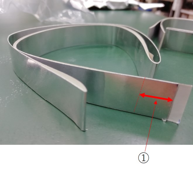
① Cut 20mm from the end
1 Preparation
Procedure
- Move table to home position, fully out and down.
- Remove right side gantry cover.
Refer to Parts Replacement → Gantry → Enclosure → (Cover Removal Procedure).
- Stop the rotor of X-ray tube in case of Liquid Bearing Tube before HVDC off. Refer to Liquid Bearing Tube Rotor stop procedure for details.
- Turn OFF the Axial Drive and HVDC switches on the gantry’s Service Switch Panel.
- Position the detector at 6 o'clock and lock gantry rotation.
- Turn OFF the 120 VAC switch on the gantry’s Service Switch Panel.
- Remove the gantry left side cover, top covers and front cover.
2 Removal Procedure
Procedure
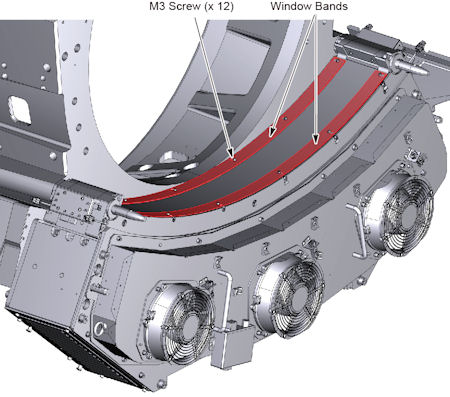
- Remove 12 M3 screws holding the detector window bands (top and
bottom) to the collimator rails, and remove the window bands.
Figure 4. Detector Window Bands
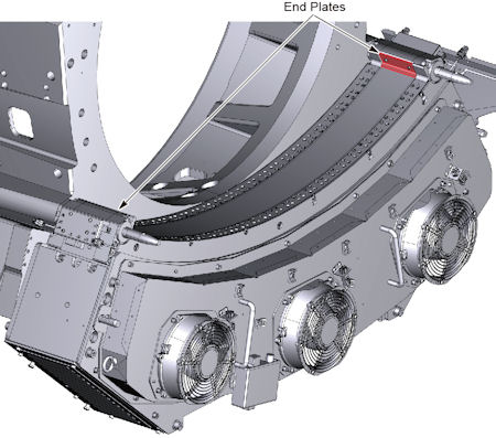
- Remove 2 (x 2) M3 screws holding the end plates to the detector
end block, and remove the end plates (detector has one on each side).
Figure 5. End Plates
 caution
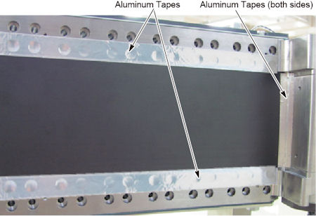
- Peel off aluminum tapes from the detector.
Figure 6. Aluminum Tapes
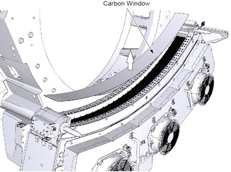
- Carefully pull up the detector carbon window and remove it from
the detector.
Figure 7. Carbon Window Removal
 |
3 Installation Procedure
Procedure
- Put the new carbon window in place.
- caution
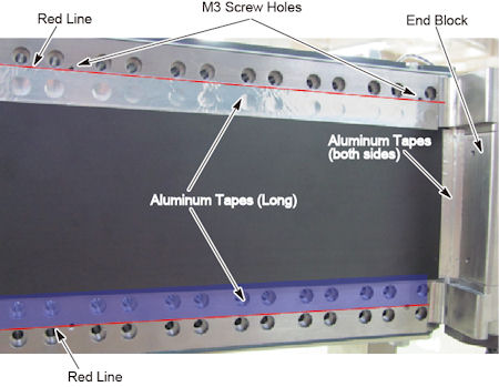
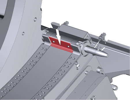
- Attach long aluminum tapes so that the edge of aluminum tape
is positioned on the red line as shown in illustration below, and
attache short aluminum tapes to the end blocks on both sides of detector.
Figure 8. Aluminum Tapes Attachment
- Put the end plate and tighten the 2 screws temporarily, then
push the end plate against the carbon window and tighten the 2 screws
to fix it.
Figure 9. End Plate Installation
- Install the other end plate to the other side in a similar way to above step.
- Install the detector window bands (to and bottom), and tighten the 12 screws.
- Confirm that the aluminum tape does NOT stick out from the bands. It may cause of artifact.
|
4 Gantry Reassembly
Procedure
- Make sure the Axial Drive, HVDC and 120 VAC switches on the gantry’s Service Switch Panel are OFF.
- Release the gantry rotational lock and install gantry covers,
all except the right side cover.
Refer to Replacement → Gantry → Enclosure → (Cover Removal Procedures).
- Turn on the 120 VAC, HVDC and Axial drive service switches.
- Install gantry right side cover.
5 Finalization
Procedure
- Run FastCal. note:
If Detailed Cal was previously run with the damaged detector window, then a full Collimator Cal, Detailed Cal, and FastCal will be required, NOT just a FastCal.
- Perform a System Scanning Test from the [Functional Checks] menu of the service manual.