- Topic ID: id_27213833
- Version: 4.0
- Date: Dec 29, 2020 12:56:16 AM
Cradle Extender and Head Holder Latch Replacement
Prerequisites
Overview
This procedure is applicable to both the cradle extender and patient head holder latches for all NG table models. Only the cradle extender is shown within this procedure, but the replacement process is the same for the patient head holder.
The replacement latch kit is shown in Figure 1 below. The movable lever (Item 2) is designed to be removed for access to the mounting screws by popping the lever pivot arm from the latch base plate (Item 1). The lever can be easily pop off if the cradle extender is placed on a hard surface in a rough and haphazard way, leading the customer to believe either the latch is broken, or simply pops the lever back in place. Over time the lever pivot arm or the mating slot on the base plate becomes worn and the assembly must then be replaced.
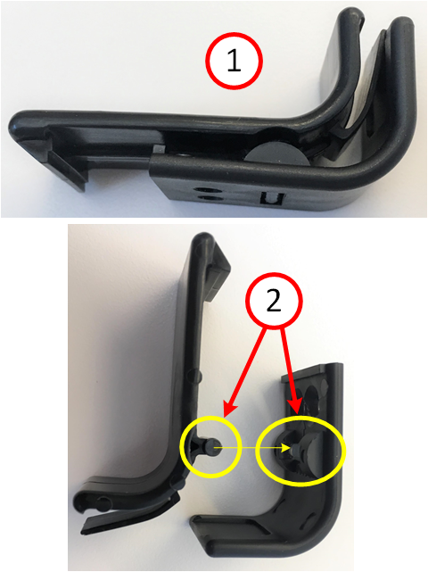
Figure 2 shows the latch assembled (top frame) and separated (bottom frame). If the lever pivot arm or the mating slot appears worn or damaged, the assembly must be replaced.
Figure 1. Latch Kit
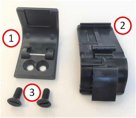
Figure 2. Inspect for Latch Damage
1 Part Removal
Procedure
- If the lever is installed in the latch base plate, use a medium flat blade screwdriver to pry the lever off. Only mild twisting action is required.
- Remove latch base plate using a flat blade screwdriver to remove the two plastic screws and dispose the old hardware. DO NOT reuse any of the old hardware.
- If necessary, using Clean Wipes and alcohol swabs as needed, clean the cradle extender surface around the old latch location.
2 Part Install
Procedure
- On the new latch assembly, if the lever is already installed in the latch base plate, use a medium flat blade screwdriver to pry the lever off.
- notice
- notice
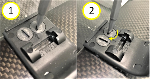
- Install the latch base plate as shown in Figure 3 below using
two new plastic screws supplied with the kit. Tighten screws only
1/8th turn past when resistance is first noticed.note:
The arrow on the latch base plate points in the direction the extender will be inserted into the table cradle.
Figure 3. Latch Mounting Screws
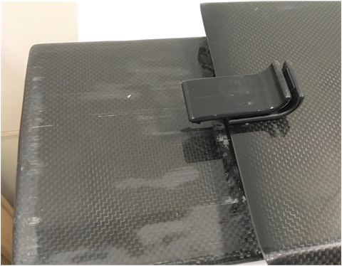
- Press the lever’s pivot arm into the slot on the latch
base plate. When properly installed the latch is oriented as shown
below:
Figure 4. Latch Orientation
 |
|
3 Functional checks, Alignments and Setups
Procedure
- Insert the cradle extender into the cradle to very the latch positively engages. Gently pull on the extender to verify the latch holds.
- Verify the lever opens far enough to release and remove the extender.
4 Finalization
Finalization
No finalization steps.