- Topic ID: id_17423427
- Version: 2.0
- Date: Jan 27, 2022 12:51:15 AM
CTPM-1707 (Lite Table PM)
Prerequisites
Overview
Procedure Effectivity:
1 Check Head Holder
Procedure
- Check each head holder on site for the following:
- The latch hook stops at each of the lock and release positions.
- The hook axis has not become weak.
- No cracks exist on the acrylic resin parts; especially inspect well the rib root (where the patient’s neck is placed), and parts around the flat head screws. If any crack is found, replace the head holder.
- No flat head screws are loose. If loosened, tighten those. (Torque: 8 kg–cm; turn the grip of the screwdriver using thumb, index finger, and middle finger, which gives approximately this torque.) Tighten the loosened screws only, and DO NOT excessively tighten the screws, which will cause cracks.
- All velcro tape is securely attached to the head holders. If not the case, replace the velcro tape.
- Check that the lock hook is securely attached to each head holder. If not, tighten the loosened flat head screw. Do not over tighten screws.
- Repeat the same check for the cradle side lock hook.
2 Check Table moving parts Grounding Connections
Procedure
- Tighten all electrical connections including grounding connections on the moving parts of the table.
3 Check Table Cover
Procedure
- Check that the Table Cover is not deformed and not damaged. Also check that the Table Cover does not interfere with the cradle.
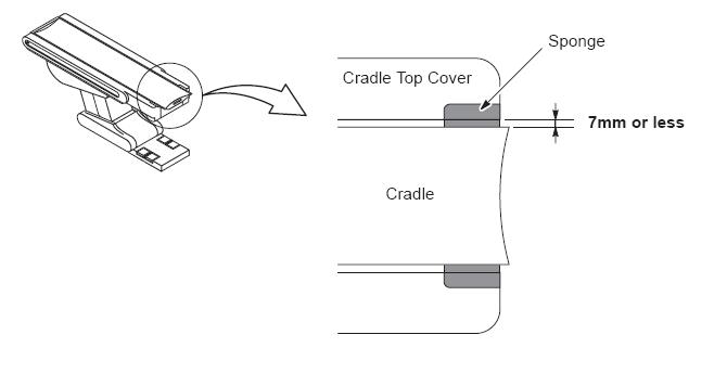
4 Check Gap Sponge
Procedure
- Check that two pieces of sponge are securely attached to the Table front end. If they have come off, replace them.
- Check the gap between cradle and sponge is 7mm or less.
Figure 1. Gap between Cradle and Sponge
5 Gap between Table Cover and Cradle
Procedure
- Check that the position of the table cover and the cradle are parallel, and the gap between them is 7mm or less.
6 Check Body Strap
Procedure
- Move the Table to its lowest position.
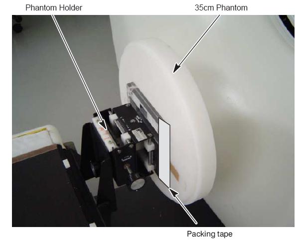
- Install the phantom holder to the cradle, then set the 35cm phantom to the phantom holder.
- Using a packing tape or equivalent, hold the phantom to the
phantom holder to prevent the phantom from dropping when lifting the
cradle.
Figure 2. Setting the 35cm phantom and phantom holder
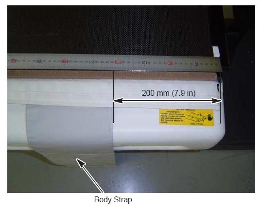
- Attach the left and right Body straps at 200 mm (7.9 in) position
from the front end of the cradle.
Figure 3. Setting the Body Strap (200mm location)
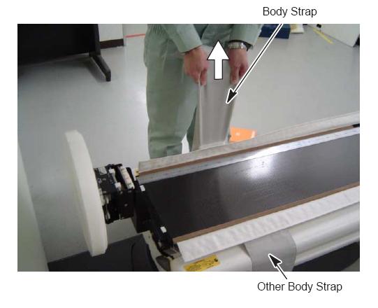
- Lift up the cradle while pulling up the body strap.
- Verify that the body strap is NOT removed from the cradle.
- Check the other side of the body strap using steps 4 to 6.
Figure 4. Lifting up the Cradle
7 Check Cradle Rail
Procedure
- Check the cradle for the following
-
Check that the Velcro tape of the cradle is securely attached. If the Velcro tape has come off, replace the cradle.
-
Check that the cradle rails are not damaged or cracked. If damaged, replace the cradle as an assembly.
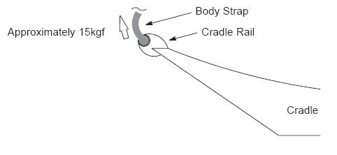
-
Set the body strap to the cradle rails, then pull the strap by the force of approx. 15 kgf, using a spring balance. Verify that the strap do NOT be removed from the rail. If not, replace the strap or cradle.
Figure 5. Cradle Rail
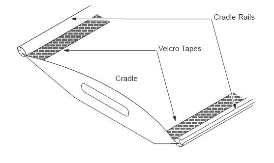
Figure 6. Body Strap Attachment
-
8 Holder Stability Check
Procedure
- Verify that the following holders is not loose by hand, when
they are attached to the cradle edge.
-
Axial Head Holder
-
Cradle Extender
-
Head Holder
-
Phantom Holder
-
Coronal Holder
-
None
-
9 Check Touch Sensor Operation
Procedure
- Press the Touch Sensor without Table movement operations, and then verify that the Table will not move DOWN when Table DOWN SW is pressed.
- Repeat this for all touch sensors.note: To resume the Table down motion, first move the Table slightly UP, then perform the Table DOWN operation.
10 Clean Cradle tray / Table Cover
Procedure
 caution
- Clean Table covers and cradle.
-
Clean dust from the Table top cover (tray) using a vacuum cleaner.
-
Clean the Table covers.
-
Be sure to wipe off contrast from the cradle edge extrusion.
-
 |
11 Check for Oil Leak
Procedure
- Verify that no oil has leaked from the cylinder, pump, hoses, etc. Verify that the Table does not lower on its own when the Table is left unoperated for some time.
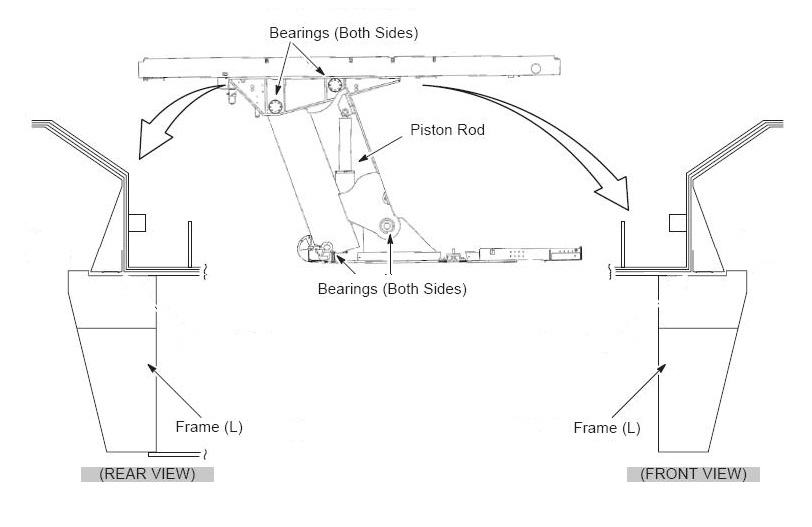
12 Grease-Up
Procedure
- Remove the both sides Table covers and bottom Table covers.
- Apply grease (SHELL ALVANIA grease #2 or equivalent) to the
following portion. (Pack grease between the inner and outer races
of the ball bearing using your finger.)
-
Joint Bearings (total eight(8) bearings) of the Table Linkage
-
Piston Rod Surface of the Hydraulic Cylinder
-
Frame Rail and of Cradle Assy
-
- Wipe off any excess grease.
Figure 7. Joint Bearings & Piston Rod
13 Table Anchor Inspection
Procedure
- Check to see if any of the anchor washers can be moved by hand.
-
If moveable, re-torque to 50 ± 6 Nm (37 ± 5 ft. lbs.).
-
If re-torqued, add a new visual inspection mark with a permanent marker (or tamper-prof paint) by drawing a line across the nut, shaft and washer.
-
14 Functional Check
Procedure
- Record the distance from ISO center ”V” by selecting “view values” on Mechanical Characterization in Characterization menu of CSD.
- Tilt the gantry to zero degrees if it is not already there.
- Move he cradle to the home position.
- Use the Table Down gantry push-button to lower the table to the minimum height.
Expected Result: The elevation display should red 550+V ± 3 mm.
- Raise the table to the maximum height using the gantry controls.
Expected Result: Elevation display should read V ± 3 mm.
note:If the mechanical alignment of the table/gantry is not correct, these values may be out of range. Most of the following tests will still be valid.
- Move the cradle height to 154 mm.
- Move the cradle in to 1000 mm.
- Tilt the gantry to S30 and verify the table height can be adjusted from 154 mm to V mm.
- Move the cradle height to 72 mm, and tilt the gantry I30.
Expelcted Result: The tilt display should read I30. The table lower limit should be 72 ± 3 mm. The upper table limit should be V ± 3 mm.
- Use the home switch to return the gantry and table to the home position.
15 Finalization
No finalization steps.