- Topic ID: id_17423022
- Version: 4.0
- Date: Nov 6, 2020 1:29:53 AM
Axial Encoder Assembly Replacement
Prerequisites
Overview
This replacement procedure defines the replacement process for the axial encoder.
Procedure
- Remove gantry right side cover.
Refer to
- Stop the rotor of X-ray tube in case of Liquid Bearing Tube before HVDC off. Refer to Liquid Bearing Tube Rotor stop procedure for details.
- Turn OFF the Axial Drive and HVDC switches on the gantry’s Service Switch Panel.
- Rotate the gantry to place the tube at about the 7 o'clock position
for easier access to the encoder.
Figure 1. Tube Position

- Turn OFF the 120 VAC switch on the gantry’s Service Switch Panel.
- Remove the gantry left side cover, top covers and front cover.
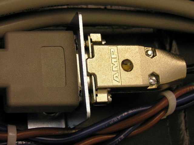
- Disconnect the Encoder DB-9 pin connect from the gantry harness
on the gantry frame above the encoder. See Figure 2.
Figure 2. Encoder DB 9-Pin Connect
- Carefully cut cable ties as necessary.
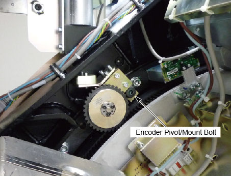
- Using the 8 mm hex key, remove the shoulder screw on which the
encoder assembly pivots.
Figure 3. Encoder pivot/mount
- Install the new encoder assembly, route and connect the cable.
- Slide shoulder bolt into encoder assembly so the threads are sticking out the back.
- Apply a minimal amount of Loctite 242 to the tip of the shoulder bolt threads. This is to insure that the Loctite does NOT wick out onto the shoulder of the bolt and mix with the grease.
- Position the assembly and thread the bolt into the stationary base frame.
- Torque the mount bolt to the following:
- Replace any cable ties removed during part removal.
- Perform the Resetting the C-Pulse procedure.
- Install the gantry front, top and left side covers.
Refer to
- Enable 120 VAC HVDC and Axial Drive service switches from the service switch panel. Press the table drives enable button on the lower right corner of the service switch panel.
- Install the gantry right side cover.
Finalization
- Perform a System Scanning Test from the Functional Checks menu of the service manual to ensure system operation.