- Topic ID: id_17423021
- Version: 4.0
- Date: Dec 29, 2020 1:03:01 AM
Axial Drive Assembly Replacement
Prerequisites
Overview
This demonstrates how to replace a 2010 Axial Drive assembly.
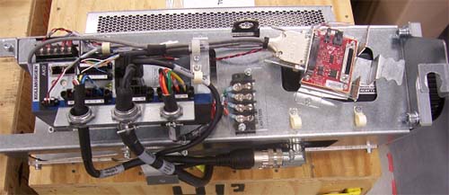
Figure 1. Drive Assembly to be installed
1 Preparation for Replacement
Procedure
- Stop the rotor of X-ray tube in case of Liquid Bearing Tube before HVDC off. Refer to Liquid Bearing Tube Rotor stop procedure for details.
- notice
- Remove gantry right side cover and disable Axial drive, HVDC and 120 VAC service switches from the Service Switch Panel. For cover removal refer to Replacement > Gantry > Enclosure > Cover Removal Procedure.
- Perform all required LOTO activities to remove all power from the Gantry.
- Remove the gantry left, top and front covers. And slide out the rear cover.
- Remove the right side tilting safety cover with a 5mm hex wrench.
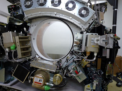
- Position the tube to 6:30 o’clock position so that there
are minimal obstructions from the hoist setup to the drive/motor assembly
position. See Figure 2.
Figure 2. Gantry Positioning
- Engage the rotating assembly indexer lock to prevent gantry rotation during this procedure.
- notice
- Remove the lower slip ring cover screw and slide into the lower
right slip ring cover in order to access the belt tension adjustment
screws. See Figure 3.
Figure 3. Lower Slip Ring Cover
 |
|
2 Removal of existing axial drive assembly
Procedure
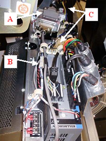
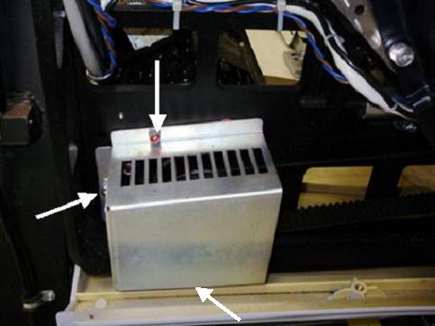
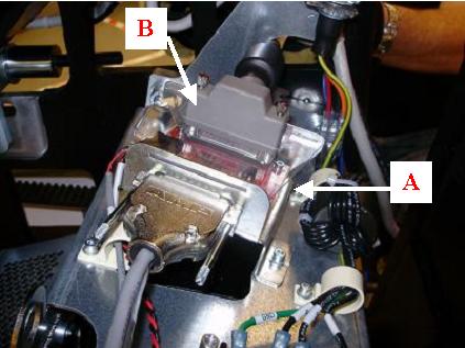
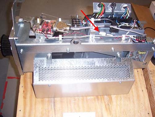
- Disconnect the axial power cable, holding brake cable and TGPU
cable from existing axial drive and pull excess wires through the
back of the frame. See Figure 4.note:
To disconnect the power cable ends from the terminal strip, removal of power strip cover is necessary.
Figure 4. Power cable, brake cable and TGPU cable to be disconnected.
- Remove the drive gear cover by removing the two or three M6
hex screws, flat washers and washer locks. See Figure 5 below.
Figure 5. Gear Cover
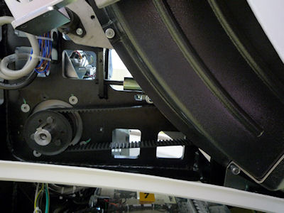
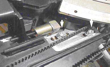
- Loosen the axial drive belt. Refer to Figure 6.
- Using a 10mm hex key, or hex bit socket, loosen the two mounting screws on the plate.
- Using a 6mm hex key, or hex bit socket with a 12-in. extenstion,
fully loosen the elongated hex screw to loosen the drive belt.
Figure 6. Threaded rod and 2 mounting screws
- Remove the drive belt from the drive gear. Take care to not disturb the teeth engagement along the rotating assembly.
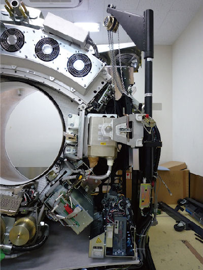
- Assemble the gantry tube hoist frame and install hoist. Clip
the end of the chain to the hoist ring on the axial drive to support
the drive assembly (see Figure 7).
Figure 7. Hoist Attachment
 warning
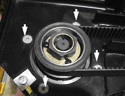
- Using a 7/32-in hex bit socket, remove the four (4) hex screws
mounting the motor to the gantry frame. See Figure 8.note:
Screws may be very tight, be careful when initially loosening motor mount screws.
Figure 8. Removing the four (4) hex screws will release motor.
- warning
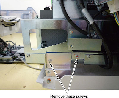
- Remove two screws from the drive assembly (see Figure 9).
Figure 9. Screws of Mounting Axial Drive
- Guide the motor assembly out of the gantry and set aside. Leave the hoist assembly set up as it will be required for the installation of the new drive.
3 Installing Axial Drive Assembly
Procedure
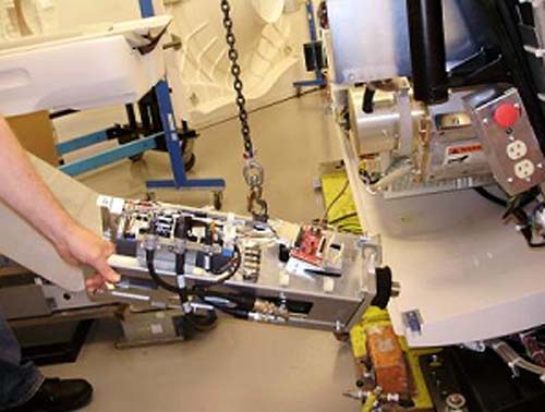
- Attach new drive assembly to the hoist via the hook on top of
the box. The drive will tilt downward on the motor end of the assembly
after lifting it off the ground. See Figure 10.
Figure 10. Mounting drive assembly to hoist
- Guide the drive into position and pivot so the drive is in correct
orientation with the frame. See Figure 11 below.
Figure 11. Guide drive into position
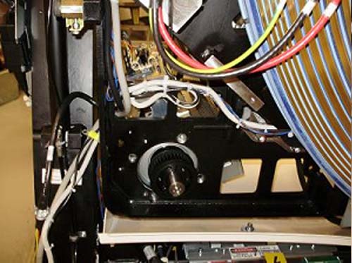
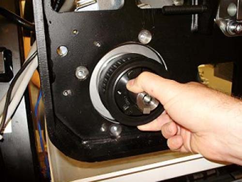
- Rest guide on hole in back frame, then position so bolt holes
line up. May have to pull back on drive slightly. Refer to Figure 12 below:
Figure 12. Pull back on motor hub to hold in place before bolting to frame.
- Bolt motor to frame from the back. Torque according to table.
- Remove hoist once assembly is mounted. Attach two mounting screws. See Figure 9.
4 Cable Installation and Routing
Procedure
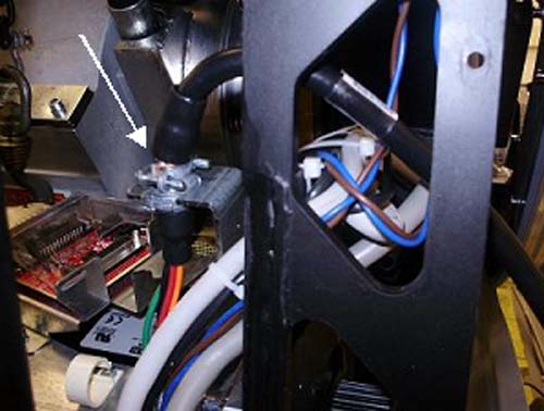
- Pull power cable through gantry frame above the motor mount.
Clamp cable in bulkhead. See Figure 13 below.
Figure 13. Routing of axial drive power cable
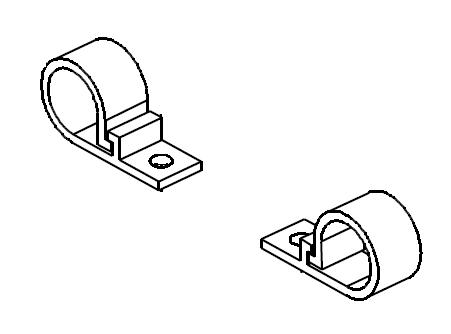
- Guide wire bundle through two plastic cable clamps toward terminal
strip. Refer to Figure 14 for visual reference of cable clamps.
Figure 14. plastic cable clamp diagram
- Remove the cover from the terminal strip.
- Loosen the screws on motor side of terminal strip with a flat head screwdriver.
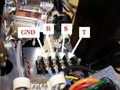
- Connect wires into terminal strip as follows (L to R): “GND”,
”R”, “S”, “T”. These should line
up with neighbor wires from the 2010 Axial Drive, and torque according
to table below. See Figure 15 for orientation of the wires.
Figure 15. Terminal strip connections
- Tighten screws and re-install cover.
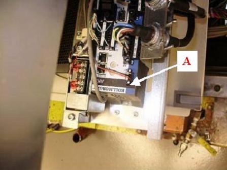
- Guide TGPU cable over bracket and connect to the back of the
KIM board assembly and tighten the two (2) Velcro straps around TGPU
cable and bracket. See illustration below.
Figure 16. Routing and connection of TGPU cable
- Pull the holding brake wire (blue and brown) through and connect
to the power supply assembly. See Figure 17 below.
Figure 17. Connection of holding brake wire
- Replace belt around motor hub and tighten belt.
Refer to Align, Setup, Calibrations > Gantry > CT Belt Tension Check & Adjustment.
- Replace gear cover and torque according to Table below. See Figure 5 as a reference.
5 Re-Assemble of Gantry
Procedure
- Fix the lower slip ring cover and install the tilting gantry safety cover.
- Remove LOTO to restore system power.
- Connect the front cover cables.
- Turn on the 120 VAC service switch from the Service Switch Panel.
- When power is turned to ON, a code “o2”
should display on the axial drive window. See Figure 18 below:
Figure 18. o2 Display
- Turn off the 120 VAC service switch from the Service Switch Panel.
- Re-install right side tilting gantry cover.
- Disengage rotating assembly lock and reassemble bottom cover, then install lower slip ring cover.
- Install the gantry front and rear covers, scan window, then the top and left side covers.
- Turn on the 120 VAC, Axial Drive, and HVDC service switches from the Service Switch Panel.
- Install the gantry right side cover.
6 Finalization
Procedure
- Perform a Fastcal from theDaily Prep button of the scan display.
- Run the System Scanning Test from the Functional Checks procedure list.