- Topic ID: id_17423078
- Version: 4.0
- Date: Dec 3, 2019 1:48:49 AM
zalignmentWizard User Instructions (Merc40)
The zalignmentWizard is used to check the relative alignment of all detector modules in the detector. The key alignment is module to module across the detector for z axis. Each module must be within a specified distance of the module on each side. That means, for example, module 3 must be closed in alignment to both module 2 and module 4. In Merc40 detector, Detector module position is not adjustable, therefore this tool is used for the purpose of alignment confirmation
1 General Instructions
The alignment check is automatically run by the MiniCheck process in the FRDM Replacement Wizard.
Press the Scan Start button when requested. After the scan completes, automated processing will start and the following plot is displayed in approx. 2 minutes as shown in Figure 1.
Figure 1. Alignment Plot Window
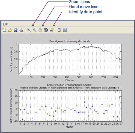
The following features as shown in Illustration 1 are available.
-
Save the plot as a jpeg, gif, tiff, from the File menu – “Save as” feature.
-
Zoom in and out using magnifying glass icons.
-
Shift displayed plot within window using the hand icon.
-
Identify data point using cursor select. After displaying the value of plot, you can change the plot by using arrow key of keyboard.
The top graph shows the complete detector module absolute positions. The plot typically shows stair step divisions each of which is 16 channels of one detector Chiclet. Modules exactly in alignment with each other will show as a continuous line.
The bottom graph shows the Chiclet positions with respect to its neighbor. Each data point is the difference from next Chiclet position. One detector module contains four Chiclet, horizontal axis shows the module number, but the cross cursor is twice number. Last Detector module shows only one Chiclet.
The following shows how to identify the difference of inner module and between modules.
Figure 2. Module and Chiclet Boundary and measurement
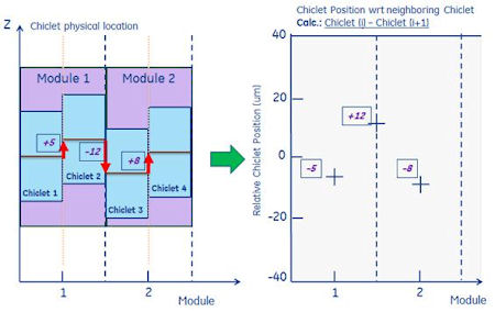
In this picture, Chiclet 1 and 2 are in Detector module 1, Chiclet 3 and 4 are in Detector module 2.
The difference within one Detector module is not adjustable. This is precisely adjusted at manufacturing. Also the Detector module position is decided by modular collimator. The play is approx. 5 microns, it’s not adjustable.