- Topic ID: id_17423249
- Version: 1.0
- Date: Aug 23, 2018 11:10:20 PM
Equipment Service – Lockout Tagout PPE
|
|
|
Follow these general rules:
-
All installed GE Healthcare systems require a LOTO compatible Main Disconnect to lock out power going to the GE system PDU.
-
Only qualified service personnel trained in the service and operation of this scanner, options, and accessories should perform any service on this equipment. Service personnel must observe and apply LOTO as defined by annual LOTO training.
-
Equipment fuses, switches, and circuit breakers are for fire and equipment protection only. Do not rely on them to protect you against electrical shock or un-commanded equipment motion. This includes the Gantry Service Switch Panel!
-
Personal Protection Equipment (PPE) is required and must be worn.
The service switches and circuit breakers described hereafter are not to be relied on as personal protection devices. They do not replace lockout and tag out of main power to ensure personal safety. Switches and breakers are intended to only inhibit particular system functions and equipment operation during troubleshooting. They do not eliminate or remove the electrical or mechanical hazards that exist. Because hardware can fail and defeat the functionality of these devices, only Lockout/Tagout ensures protection from energy sources.
Personal protection equipment must always be used when performing service on this equipment. Always use PPE when working with hazardous chemicals or materials.
Below are the location/definition of the energy sources that exist in the system followed by the Lock Out Tag Out/Safety procedures relating to the energy sources in the system organized by subsystem. Be familiar with these procedures as they are referenced in the service procedures when appropriate.
Common procedures across subsystems are contained in Procedures and will be referenced by the subsystems as applicable.
1 Scanner Desktop I and II (Operator Console)
1.1 Electrical Energy
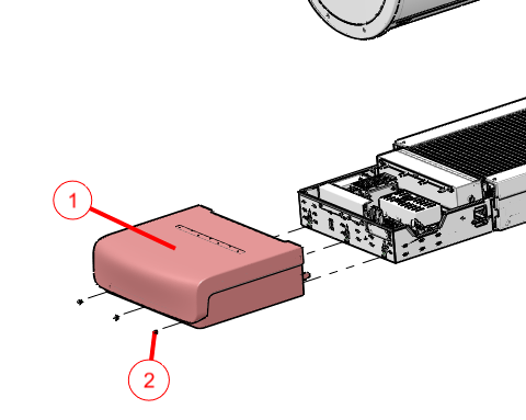
Figure 1. Scanner Desktop I Cabinet Power Inlet Location
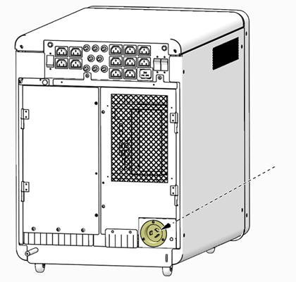
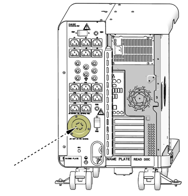
Figure 2. Scanner Desktop II Cabinet Power Inlet Location
1.2 Thermal Energy
Though the potential exists where temperatures of components in the Scanner Desktop may exceed safe threshold for personal handling (ex: short circuit failure), generally temperatures should not exceed 50 degrees C / 122 degrees F (worse case condition). Before handling any components in the Scanner Desktop, allow a few minutes to pass after power off condition has been confirmed.
2 System Cabinet
2.1 Electrical Energy
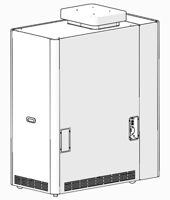
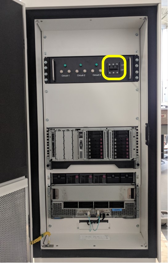
Figure 3. System Cabinet I – Power Inlet Location
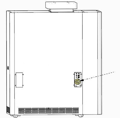
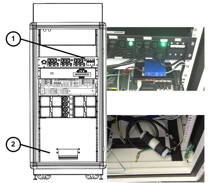
Figure 4. System Cabinet II, III, and IV– Power Inlet Location — Item 2
2.2 Thermal Energy
Though the potential exists where temperatures of components in the System Cabinet may exceed safe threshold for personal handling (ex: short circuit failure), generally temperatures should not exceed 50 degrees C / 122 degrees F (worse case condition). Before handling any components in the System Cabinet, allow a few minutes to pass after power off condition has been confirmed.
3 Gantry
3.1 Electrical Energy
The electrical power for the gantry is a direct feed from the PDU to the gantry power pan. The connection at the gantry are the large round power plugs at the rear base of the gantry behind the base covers.
The primary lock out method is full system power down with the lock out at the A1/Main Disconnect Panel.
3.2 Mechanical Energy
When the system is powered up, the axial drive controls the rotating assembly. However, when the gantry is powered off, the rotating assembly is free to rotate. The rotating assembly is a tightly balanced set of components. Removal of any item will cause the rotating assembly to suddenly want to turn. To prevent this from happening, engage the Rotational Service Lock located on the front left or right side of the gantry. These locks slide into predefined positions and have a safety cover that allows the latch to be locked out using the LOTO lock. Refer to Figure 27.
3.3 Thermal Energy
There are numerous components on the gantry that can become hot during operation. These are the following:
-
Tube
-
Inverter
-
Axial Brake Assembly
Care must be taken to pay attention to the hot surface warning labels and waiting the appropriate length of time defined by the service procedures prior to accessing and servicing the component.
4 PDU
4.1 Electrical Energy
The PDU is the electrical power distribution for the system. The power comes from the A1/Main Disconnect Panel and is hard wired to terminal connectors inside the PDU. There are no “plug” connections to or from the PDU.
Due to this the only Lock out location is the A1/Main Disconnect Panel.
4.2 Stored Energy
The PDU has large capacitors that do store energy for a brief period after power is shut down. Care must be taken to wait for that power to dissipate after power is removed from the system.
5 Table
5.1 Electrical Energy
The table electrical energy comes from the system PDU through the Gantry power pan. Power is the form of 120VAC and 24V DC is routed through connectors at the front base of the table. The only location available for locking out power to the table is the system A1/Main Disconnect panel.
5.2 Mechanical Motion
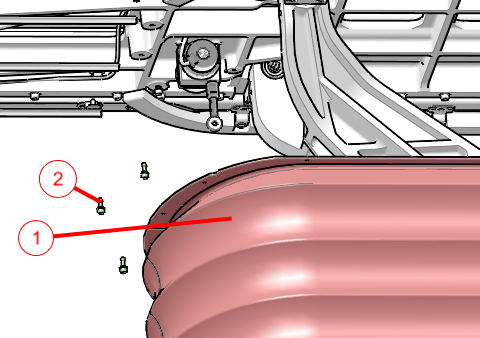
The table is designed to move up and down and is driven by an electric motor screw drive to operate a scissor action table support. Failures within the drive could cause the table to move down without external commands. The table has a lock bar under the right side top rail, beneath the bellows, for use with a LOTO lock to prevent motion during service repair actions.
Figure 5. Table LOTO Lock Position
6 Procedures
6.1 A1/Main Disconnect Panel LOTO
The A1/Main Disconnect Panel is the location to lock and tag a system for full electrical isolation.
-
Prepare for shutdown of equipment. Notify affected personnel working in the area, via verbal communication, that LOTO is being performed.
-
Bring the system software down at the Scanner Desktop.
-
After software shutdown is complete, press the emergency stop button on the A1 Panel or Disconnect Panel.
-
If there is an on/off switch controlled by a key, turn to off position.
-
All personnel servicing the system must place their personal LOTO devices and tags on the A1 Panel of Main Disconnect Panel. See Figure 6.
-
Verify that all energy has been dissipated as follows. Take the top and front cover off the PDU. Measure incoming system power at TS1 (for NGPDU). Measure each phase to ground with a DVM (Voltage measuring device) and verify electrical power is not present.
-
Wait 5 minutes for any stored energy in capacitors to dissipate.
-
Service/repair the CT system per service instructions.
Figure 6. A1/Main Disconnect Panel Example
6.2 Bevco A1 Main Panel LOTO
The A1/Main Disconnect Panel is the location to lock and tag a system for full electrical isolation.
-
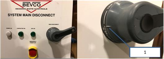
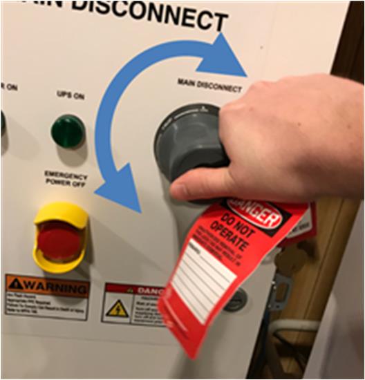
Ensure the handle is all the way into the “OFF” position. This is indicated by the handle position indicator pointing to the “OFF” text.
Figure 7. : Main Disconnect Panel showing proper “OFF” position
-
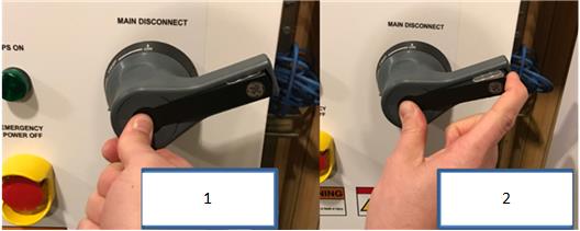
Once the handle is in the “OFF” position, press the center of the handle and lift out the back of the handle, exposing the holes for the installation of LOTO locks.
Figure 8. Steps to expose the LOTO lock locations on handle
-
Once the LOTO lock is applied, attempt to rotate handle to ensure the handle will not turn the panel on, as shown in Figure 3, below. If the handle is able to rotate such that the panel could turn on, rotate as far as possible in a counter-clockwise direction and try turning the handle back on again.
Figure 9. Attempt to rotate the handle after the LOTO lock is applied to ensure the handle will not rotate and turn the panel on.
-
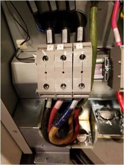
With your PPE (Category 2) on, confirm power is off by checking power with your multi-meter at Terminal 1 on the PDU.
Figure 10. Terminal 1 Location
6.3 Scanner Desktop I and II LOTO
The Power Inlet connection on the Scanner Desktop cabinet is the location to lock and tag a the Scanner Desktop for electrical isolation.
-
Prepare for shutdown of equipment. Notify affected personnel working in the area, via verbal communication, that LOTO is being performed.
-
Bring the system software down at the Scanner Desktop.
-
After shutdown is complete, place Scanner Desktop I Chassis Circuit Breakers/Switches (CB–1, 2 and 3) or Scanner Desktop II Chassis Circuit Breakers/Switches (CB–1 and 2) in the OFF position.
Figure 11. Scanner Desktop I Chassis Circuit Breakers/Switches
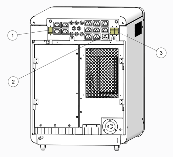
Figure 12. Scanner Desktop II Chassis Circuit Breakers/Switches
-
Disconnect the AC power cable from the Scanner Desktop chassis power inlet. See Figure 1.
-
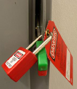
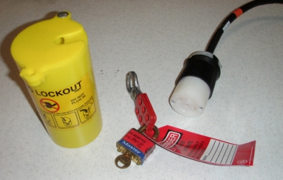
All personnel servicing the system must place their personal LOTO devices and tags on the AC Line cord Plug Lockout Canister.
Figure 13. Personal LOTO devices and tags
-
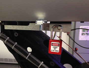
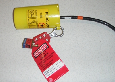
Using the Plug Lockout Canister, lockout the AC Line cord once removed from the Scanner Desktop chassis.
Figure 14. AC Line Cord Locked
6.4 System Cabinet I – LOTO
The Power Inlet connection on the System Cabinet Bulkhead Panel is the location to lock and tag a the System Cabinet for electrical isolation.
-
Prepare for shutdown of equipment. Notify affected personnel working in the area, via verbal communication, that LOTO is being performed.
-
Bring the system software down at the Scanner Desktop.
note:Shutting down the Scanner Desktop will also perform a shutdown of the System cabinet computers via the system’s network interface. Power is still applied to the System Cabinet, and the computers will placed in standby mode.
-
Power Off the System Cabinet by disconnect the AC power cable from the System Cabinet power inlet. See Figure 3.
-
All personnel servicing the system must place their personal LOTO devices and tags on the AC Line cord Plug Lockout canister. See Figure 13.
-
Using the Plug Lockout Canister, lockout the AC Line cord once removed from the System Cabinet chassis. See Figure 14.
6.5 System Cabinet II, III, and IV– LOTO
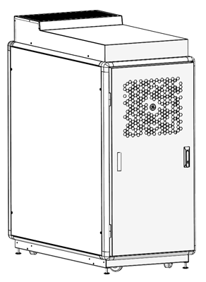
The Power Inlet Twist-n-Lock connector inside the System Cabinet chassis is the location to lock and tag a the System Cabinet for electrical isolation.
-
Prepare for shutdown of equipment. Notify affected personnel working in the area, via verbal communication, that LOTO is being performed.
-
Bring the system software down at the Scanner Desktop.
note:Shutting down the Scanner Desktop will also perform a shutdown of the System cabinet computers via the system’s network interface. Power is still applied to the System Cabinet, and the computers will placed in standby mode.
-
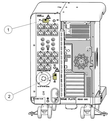
Power Off the System Cabinet by turning off the Circuit Breaker (Item 1 in Illustration below) inside the System Cabinet and disconnect the AC Power Inlet Twist-n-Lock connector (Item 2 in Illustration below). The Circuit Breaker in System Cabinet IV is located at the front of the PDU.
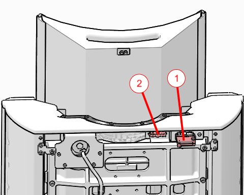
Figure 15. System Cabinet II & III LOTO
Figure 16. System Cabinet IV Circuit Breaker
-
All personnel servicing the system must place their personal LOTO devices and tags on the AC Line cord Plug Lockout canister. See Figure 13.
-
Using the Plug Lockout Canister, lockout the AC Power Inlet Twist-n-Lock connector once disconnected. See Figure 14.
6.6 NGPDU LOTO
Before opening the PDU for any service action perform the following steps.
-
Bring the system software down at the Scanner Desktop.
-
After shutdown is complete, power off the entire system at the A1/Main Disconnect Panel.
-
Apply full system LOTO per A1/Main Disconnect Panel LOTO.
-
Wait 5 minutes after powering down the PDU to ensure all energy stored in capacitors has dissipated.
6.7 Table LOTO
The table electrical energy comes from the PDU through the gantry. Before opening the Table for service actions perform the following steps as required by the service procedure.
-
Use the Gantry keypad to fully retract the cradle and base to the HOME position.
-
Use the Gantry keypad to raise the table to maxim elevation.
-
Remove the Rear and Front Collision Sensor covers shown in the Illustrations below. Disconnect the front collision tape sensor harness and move the Service Shorting Plug from its storage location to the Service Position shown in Illustration.
note:These covers must be removed to expose the bellows mounting screws.
note:The Shorting Plug must be installed in the Service position to allow table movement while in Service Mode.
Figure 17. Bottom Rear Collision Sensor Cover
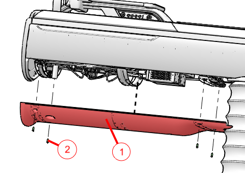
Figure 18. Bottom Front Collision Sensor Cover
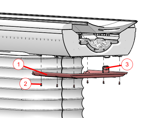
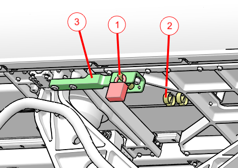
Figure 19. Collision Sensor Shorting Plug
-
Remove the Base Back Cover shown in Illustration for access to the RTCB Service panel within the electronics cage.
Figure 20. Base Back Cover Removal
-
Drop the upper bellows shown in Illustration to expose the LOTO clevis.
Figure 21. Top Bellows Upper Ring Removal
-
Refer to Illustration for Service Panel switches located on the RTCB. Press the AXIS_SEL button until the ELEV LED is ON. With the SPEED switch set to SLOW, use the DIRECTION switch (UP or DOWN) to adjust table height until the hole in the LOTO clevis lines up with the outer locking hole shown in the Illustration below. Move LOTO pin from storage location and insert into aligned holes. Attach LOTO lock.
Figure 22. RTCB Service Panel
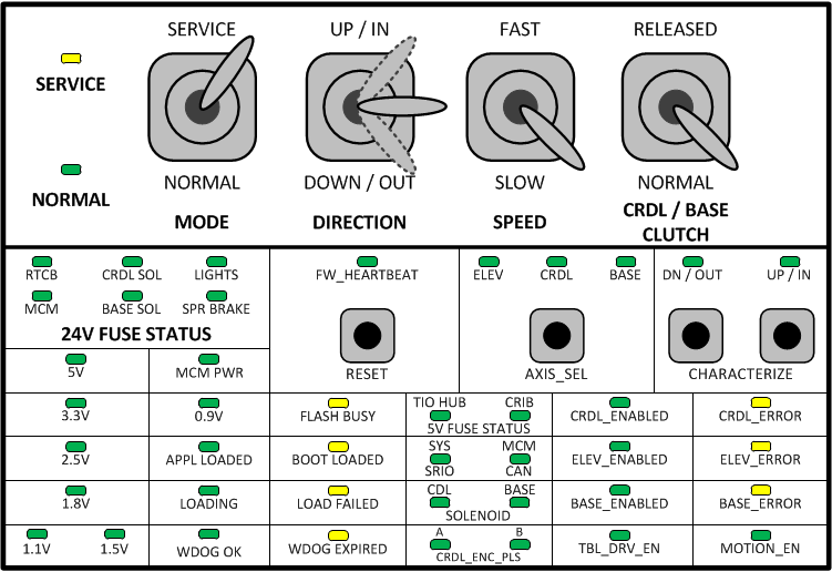
Figure 23. LOTO Locking Pin in Service Position
-

 warning
-
Shut down in the system in the following sequence:
-
Bring the system software down at the Scanner Desktop.
-
After shutdown is complete, power off the entire system at the A1/Main Disconnect Panel.
-
Apply full system LOTO per A1/Main Disconnect Panel LOTO. Wait at least two minutes before verifying power is OFF at the table electronics cage. After two minutes all LEDs on the RTCB, MCM’s, and 160V power supply should be OFF.
6.8 Gantry LOTO
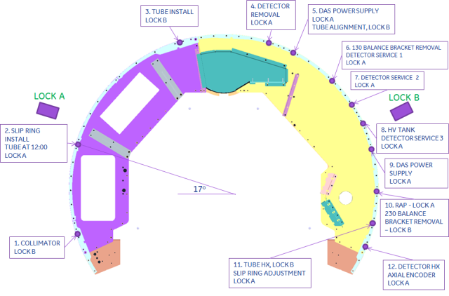
The gantry Rotational Service Lock is used to lock the rotating assembly in place and prevent it from moving. When looking at the front of the gantry, Lock A is located on the left and Lock B is on the right. Either lock can be used to hold the gantry in place. Depending on the service event, a predefined position from Figure 24 Gantry Service Lock Positions may give the best service access. Follow the instructions below to engage the Rotational Service Lock.
Figure 24. Gantry Service Lock Positions
-
Bring the system software down at the Scanner Desktop.
-
After shutdown is complete, power down gantry by turning off [Axial Motion], [Rotating Power], [HVDC] and [120VAC] service switches on GCB Front Panel (GFP).
-
Apply full system LOTO per A1/Main Disconnect Panel LOTO, if necessary.
note:Some service procedures require gantry power. Follow the specific LOTO instructions provided for those service events.
-
Open front covers or remove any covers necessary for service access.
-
Manually rotate gantry to desired location.
-
Align either Lock A or B with an Index Lock position.
-
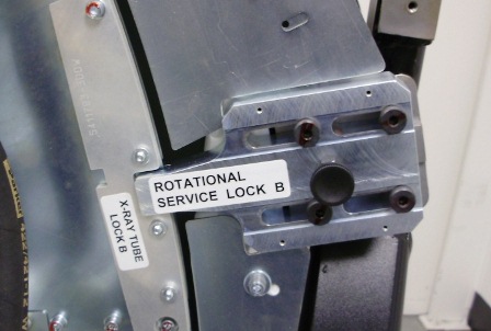
Engage Rotational Service Lock by pulling out the spring-loaded bolt in the middle and sliding the lock into locking position. The illustrations below show the Rotational Service Lock in Disengaged and Engaged positions.
Figure 25. Rotational Service Lock Disengaged
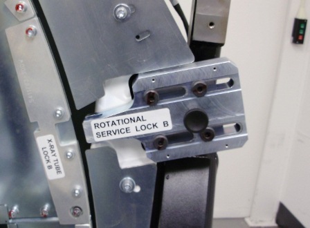
Figure 26. Rotational Service Lock Engaged
-
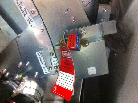
Flip the cover over the Rotational Service Lock and apply personal LOTO device and tag.
Figure 27. Rotational Service Lock LOTO
-
Reverse the steps above to remove the gantry Rotational Service Lock and system LOTO.