- Topic ID: id_11039058
- Version: 3.0
- Date: May 23, 2022 11:26:03 PM
Vyper DAS Thermistor Probe Replacement
Prerequisites
This procedure defines the replacement process for DAS thermistor probe.
1 Thermistor Probe Removal
Procedure
- Move the table cradle to the home position, and position the table to its lowest elevation.
- Remove gantry right side cover.
- notice
- Turn OFF Axial Enable, HVDC, and 120VAC switches on the service switch panel.
- Remove the rest of the gantry covers except the gantry rear cover.
- Turn ON the 120VAC switch and rotation the DAS at 12 o’clock position.
- Turn OFF the 120VAC switch and lock the gantry in position using the rotational lock.
- Disconnect the fan control cable connector and the sensor cable connector from the Vyper fan duck cover ASM.
- Remove the Vyper fan duck cover ASM by unscrewing its M6x12
head cap screws by a
 on the Vyper Fan Duck Cover.
Figure 1. Remove the Vyper Fan Duck Cover ASM

- Disconnect the inner fan control cable connector to show the thermistor probe cable connector.
- Disconnect the thermistor probe cable connector from the connector
holder.
Figure 2. Thermistor Probe Removal
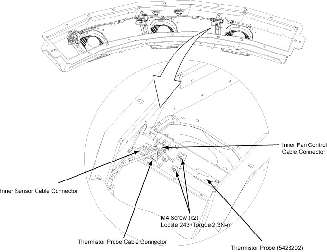
- Remove the thermistor probe by unscrewing its two M4 screws. (See Figure 2)
 |
2 Thermistor Probe Installation
Procedure
- Get the new thermistor probe and secure it with four M4 screws. (Torque: 2.3N-m + Loctite243)
- Reconnect the thermistor probe cable connector and the inner fan control cable connector.
- Reinstall the Vyper fan duct cover asm by screwing all M6 screws (Torque: 7.9N-m).
- Reconnect the fan control cable connector and the sensor cable connector to the Vyper fan duck cover asm.
- Disengage the rotational lock.
- Turn on Axial Enable, HVDC, and 120VAC switches.
- Verify that the Vyper DAS thermistor probe is operating normally.
- Restore the gantry original configuration.