- Topic ID: id_15460449
- Version: 4.0
- Date: Apr 22, 2019 12:56:38 AM
Scan Window Alignment
Prerequisites
Overview
Measure collimator and cover difference and scan window gap. Adjust as necessary. Visually inspect.
1 COLLIMATOR AND COVER DIFFERENCE
Procedure
- Remove the gantry right side cover and turn off Axial drive
from the service switch panel.
Refer to
- Remove the scan window.
- With the front and rear covers secured in place and scan window removed, rotate the collimator to the 3 o’clock position.
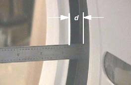
- Using an appropriate (calipers or steel ruler), measure the
distance (d) in millimeters (mm) from the collimator’s surface
to the metal scan window rim, on both the front and rear covers. Record
measurements. See Figure 1.
Figure 1. Collimator Cover Gap Distance
- If the difference |df-dr| between the front (f) and rear (r) measurements is greater than
3mm, the front cover must be shifted the appropriate direction.
For example, if the distance between the collimator and the front cover is 5.5mm and the distance between the collimator and rear cover is 10.5mm, then the difference is 5mm. The front cover must be shifted right at least 2mm. This means that mounting bracket on the front cover must shifted at least 2mm left.
-
Install the front cover dolleys and pull the front cover away from the gantry far enough to access the mounting plate on the left side (TGPU side).
-
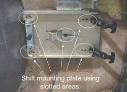
On the front cover, lightly loosen the screws securing the left mounting plate (TGPU side). Slide the plate in the direction that will give you the appropriate shift and re-secure screws. See Figure 2.
-
Install the front cover.
note:Only one mounting plate can shift so only very small adjustments of a few millimeters can be done or should be needed.
Figure 2. Gantry Cover Mounting Plate and Screws
-
- Repeat Step 4 and Step 5 until the difference between the two measurements is less than 3mm.
- Rotate the collimator to the 9 o’clock position.
- Repeat Step 4 through Step 6. Verify that a difference of less than 3mm is obtainable with the collimator positioned at the 9 o’clock position.
2 SCAN WINDOW GAP
Procedure
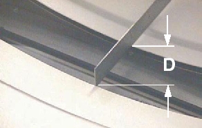
- Measure the distance (D) between front and rear covers of the
scan window rims. Measure the distance between the two covers at the
bottom of the cone. See Figure 3.
Figure 3. Scan Window Gap Distance
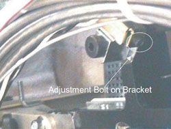
- If the spacing is the spacing is greater than 86 mm, bring the
covers together using the bolts located on the end of each cover latch.
See Figure 4.
Figure 4. Cover Bracket Adjust Bolt Location
3 VISUAL INSPECTION
Procedure
- Install the scan window.
Refer to
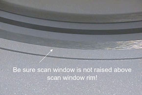
- Check that the scan window is not raised higher than the front
or rear cover at any location on the circle and that the window is
not wrinkled. See Figure 5.
If the scan window is raised above the rim, check for contrast or other contaminates on the scan window gaskets. If nothing found, order a new scan window and replace at next opportunity. A good seal is important to keep contrast or any other liquids from damaging gantry components.
Figure 5. Correct Scan Window Alignment
- Enable axial drive from the service switch panel and install the gantry right side cover.
4 Finalization
No finalization steps.