- Topic ID: id_16157621
- Version: 2.0
- Date: Nov 7, 2019 8:54:22 PM
Plane of Rotation (POR) Alignment
Prerequisites
Overview
The purpose of Plane of Rotation measurement/alignment is to put the X-ray tube in the correct physical relationship to the detector and verify it. This is normally only necessary when the X-ray tube has been replaced or moved.
Figure 1. POR Procedural Flow
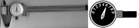
Figure 2. Vernier Caliper & Dial Gauge Indicator
(For GAFCHROMIC XR-QA Film) POR Alignment procedure, please refer to POR Alignment for GAFCHROMIC XR-QA Film.
(For Polaroid type 52 Film) POR Alignment procedure, please refer to POR Alignment for Polaroid type 52 Film.
1 POR Alignment for GAFCHROMIC XR-QA Film
1.1 For Tube Change Only
Procedure
- Wait 90 minutes if the new tube had more than 25 Kilo Joules of energy input, [KV x mA x Sec ÷ 1000] within the last 30 minutes prior to the start of system alignments.
- If a tube heat soak has been performed you must wait a minimum of 6 hours before system alignments can be performed.
1.2 Confirm Cold Tube
Make sure the tube is cold before alignments.
Procedure
- Launch the POR Alignment tool. Make sure no message pops up requiring tube cooling.
- Quit the POR Alignment tool.
1.3 Measure Tube Alignment
Procedure
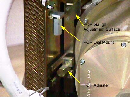
- Mount the Dial Indicator onto the Collimator / Tube Assembly
as shown Figure 3. Make sure you zero the dial indicator, when it is securely in
place.
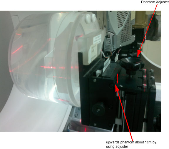
Figure 3. POR Gauge Mount and Adjuster
- Loosen the (4) M-12 bolts that secure the tube. (½ turn out is all that’s necessary, and not any more.)
- Get the system’s phantom holder and its 20cm QA phantom onto it.
- Cut film to proper size 10mm x 50mm. Cut a corner to indicate
direction later. See Figure 4.
Figure 4. Film Illustration

- Attach (1) “GAFCHROMIC XR-QA Film" on the outside edge
of the 20cm QA phantom at the 12 o’clock position.
 note:
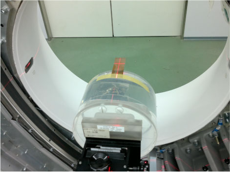
note:Only the film should be projecting into the Gantry bore when complete. The phantom is used only to position and hold the film in the gantry bore, Figure 6.
- Removed the Table Rear Bottom cover.
- Put the 20cm QA phantom on the phantom holder and adjust the
holder upward to its highest by using holder vertical adjuster.
- Adjust the 20cm QA phantom to ISO center, mark the Table height display, then using table service mode from GTCB to raise the 20cm QA phantom up ISO center 140mm
- Advance the cradle and rotate the phantom if necessary, while using the alignment lights, to position the film’s center marking on the alignment light marks.
- The old film method used a single scan with the gantry rotating.
Due to the sensitivity decrease of the GAFCHROMIC XR-QA film, and
in order to maximize the dose to the film, two Stationary scans will
be performed.
Perform two offline scans with gantry in the 0 degree and 180 degree position and as follows using the Diagnostic Data Collection menu (DDC).
Static X-Ray On
Scan Time: 3 sec
80kv
220mA
Air Filter
Large focal Spot
Slice / Collimation: 16 x 0.625
Static X-Ray On
Turn OFF Beam Tracking
- notice
- Verify that:
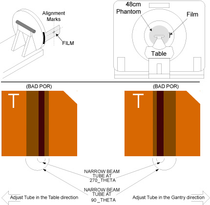
- The film’s narrow (white beam) slit lies within (between) the wider X-Ray slit.
- The film’s edges in both Z direction are equally well defined by the exit slit of the collimator. The edges of the narrow beam should be much sharper than the wide beam. If a difference in edge definition exists, check for gross Z misalignment. (Misalignment of the slit in the tube’s collimator adapter is a common cause of fuzzy film edges.)
- Refer to Figures Figure 5 and Figure 6 during the following instructions. Use a Vernier
Calipers to measure the width of the 2 wider slits. They’re
the slits that extend past the edges of the narrower slit and to the
part of the film.
- Take 3 measurements to obtain an average value for XF. Xf is the side of the film
closest to the table. Using the same film measurement tool, take (1)
Xf measurement at the top of the film, another
near the middle and another near the bottom. Add these (3) Xf distances together and divide this sum by 3 or “n”.
Where,
XF = (Xf1 + X f2 + Xf3)/(n)
note:It is important that you take multiple measurements. The more measurements you take, the more accurate the measurement. There is less likelihood of a measurement error and you will increase the accuracy of the alignment.
Figure 5. XF and XR measurement points
- Now take 3 measurements to obtain an average value for XR. Take (1) XR measurement at
the top of the film, another near the middle and another near the
bottom of the film. Add these 3 values together and divide the sum
by 3 to obtain an average for XR.
XR = (Xr1 + X r2 + Xr3)/(n)
- Use the values obtained for XF (front distance) and XR (rear distance) in the calculation that follows.
- Take 3 measurements to obtain an average value for XF. Xf is the side of the film
closest to the table. Using the same film measurement tool, take (1)
Xf measurement at the top of the film, another
near the middle and another near the bottom. Add these (3) Xf distances together and divide this sum by 3 or “n”.
Where,
- Perform as followings:
- Launch the POR Alignment tool. Select Scan.
- Press Start Scan when it flashes. In fact this scan is invalid, it only for continue to next step.
- Click on the CALCULATE button. Enter the values for XF and XR obtained in the steps above. The software will do the distance calculation.
- If the tube is out of specification, move the tube as indicated
by the program. If adjustment is necessary, clockwise rotation (in)
of adjustment bolt moves the tube towards the table side. Repeat Steps
3 through 11 again if you have moved the tube, to check accuracy of
adjustment. See Figure 6 for more details.
Figure 6. Plane of Rotation Film Interpretation
- Adjust M12 mounting bolts to pre-load torque specification.
Refer to Table 4.
- Apply final torque on all four M12 bolts according to the values
specified in Table 5.
 |
2 POR Alignment for Polaroid type 52 Film
2.1 For Tube Change Only
Procedure
- Wait 90 minutes if the new tube had more than 25 Kilo Joules of energy input, [KV x mA x Sec ÷ 1000] within the last 30 minutes prior to the start of system alignments.
- If a tube heat soak has been performed you must wait a minimum of 6 hours before system alignments can be performed.
2.2 Start the POR Software
Procedure
- Make sure the tube is cold before alignments.
- Launch the POR Alignment tool.
2.3 Measure Tube Alignment
Procedure
- Mount the Dial Indicator onto the Collimator / Tube Assembly as shown Figure 3. Make sure you zero the dial indicator, when it is securely in place.
- Loosen the (4) M-12 bolts that secure the tube. (½ turn out is all that’s necessary, and not any more.)
- Get the system’s phantom holder and its 20cm phantom onto it.
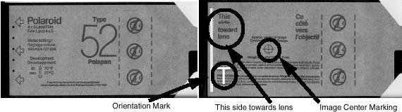
- Attach (1) “Polaroid type 52" film on the outside edge
of the 20cm phantom, at the 3 o’clock position. note:
Only the film should be projecting into the Gantry bore when complete. The phantom is used only to position and hold the film in the gantry bore, Figure 8
Orient the side of the film side marked “This side toward lens” towards iso center, see Figure 7. When exposed and developed later, the film will show the alignment of the x-ray beam with respect to the table, as viewed from the X-Ray tube in the 3 o’clock position.Figure 7. Polaroid Film, Type 52
- Advance the cradle and rotate the phantom if necessary, while using the alignment lights, to position the film’s center marking on the alignment light marks.
- Take a scan.
- Remove the exposed film and immediately mark the outside of the film nearest the table. For example, use a pen and print the letter “T” on the film nearest the table, Figure 7. Go and develop the exposed film. After the film is developed, transfer the table marking to the film itself while keeping the orientation correct, Figure 8
- Verify that:
- The film’s narrow (white beam) slit lies within (between) the wider (gray) X-Ray slit.
- The film’s edges in both Z direction are equally well defined by the exit slit of the collimator. The edges of the narrow beam should be much sharper than the wide beam. If a difference in edge definition exists, check for gross Z misalignment. (Misalignment of the slit in the tube’s collimator adapter is a common cause of fuzzy film edges.)
- Refer to Figures Figure 5 and Figure 8 during the following instructions. Use a Vernier
Calipers to measure the width of the 2 wider (dark gray) slits. They’re
the dark gray slits that extend past the edges of the narrower (off-white)
slit and to the blackest part of the film.
- Take 3 measurements to obtain an average value for XF. Xf is the side of the film
closest to the table. Using the same film measurement tool, take (1)
Xf measurement at the top of the film, another
near the middle and another near the bottom. Add these (3) Xf distances together and divide this sum by 3 or “n”.
Where,
XF = (Xf1 + X f2 + Xf3)/(n)
note:It is important that you take multiple measurements. The more measurements you take, the more accurate the measurement. There is less likelihood of a measurement error and you will increase the accuracy of the alignment.
- Now take 3 measurements to obtain an average value for XR. Take (1) XR measurement at
the top of the film, another near the middle and another near the
bottom of the film. Add these 3 values together and divide the sum
by 3 to obtain an average for XR.
XR = (Xr1 + X r2 + Xr3)/(n)
- Use the values obtained for XF (front distance) and XR (rear distance) in the calculation that follows.
- Take 3 measurements to obtain an average value for XF. Xf is the side of the film
closest to the table. Using the same film measurement tool, take (1)
Xf measurement at the top of the film, another
near the middle and another near the bottom. Add these (3) Xf distances together and divide this sum by 3 or “n”.
Where,
- Click on the CALCULATE button. Enter the values for XF and XR obtained in the steps above. The software will do the distance calculation.
- If the tube is out of specification, move the tube as indicated
by the program. If adjustment is necessary, clockwise rotation (in)
of adjustment bolt moves the tube towards the table side. Repeat Steps
3 through 11 again if you have moved the tube, to check accuracy of
adjustment. See Figure 8 for more details.
Figure 8. Plan of Rotation Interpretation
- Adjust M12 mounting bolts to pre-load torque specification. Refer to Table 4
- Apply final torque on all four M12 bolts according to the values specified in Table 5