- Topic ID: id_11038823
- Version: 3.0
- Date: Jun 10, 2020 2:30:19 AM
Phase Shift Capacitors Set Replacement
Prerequisites
Replace the phase shift capacitor set (Part no: 5175114). This capacitors set is attached on the auxiliary box
-
Remove straight cover of the auxiliary unit
-
Replace the Phase Shift Capacitors module
-
Replace cover
1 Phase Shift Capacitors Set Removal
Procedure
 danger
- Move table to its lowest elevation.
- Remove side, top and front gantry covers.
- Turn OFF all 3 switches (Axial Drive, HVDC, 120VAC) on the Service Switch Panel.
- Remove power at main disconnect panel. Use proper Lockout / Tagout procedures.
- Rotate the Gantry until the Auxiliary Assembly reaches the 3 o’clock position.
- Engage gantry rotational lock.
- Remove straight cover of the auxiliary box.
-
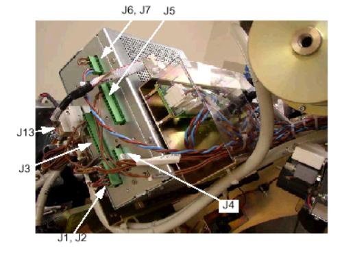
Disconnect all the cables showed in below picture:
Figure 1. Auxiliary Box Cable Connection
-
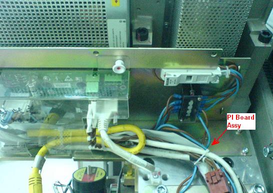
Remove four screws and put the PI board assembly at proper position.
Figure 2. Remove screws
-
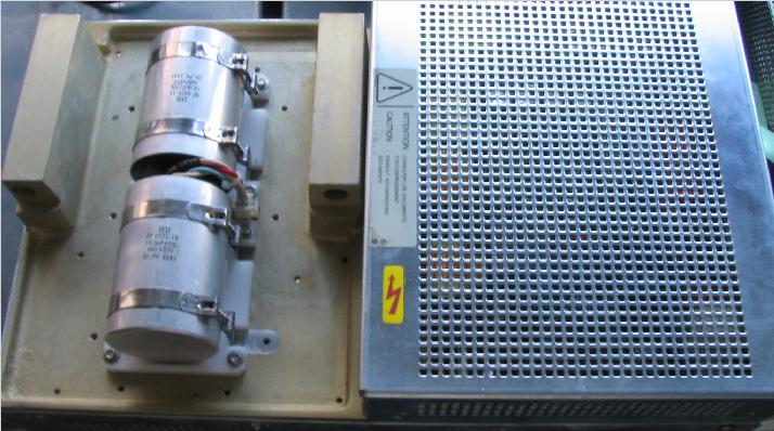
Remove ten (10) screws to remove the straight cover. Then the capacitors will appear.
Figure 3. Remove the straight cover
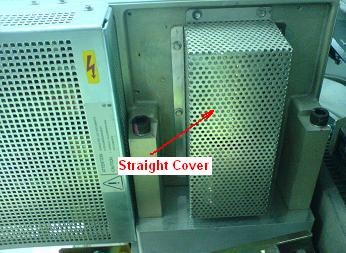
Figure 4. capacitors
-
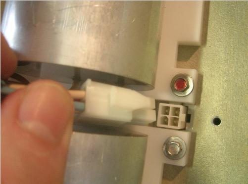
- Disconnect the following cable from the Auxiliary Casting
Figure 5. Disconnect cable from the Auxiliary Casting
- Unscrew the 8 screws around the plastic support, and remove the module from the Auxiliary Unit.
 |
2 Phase Shift Capacitors Module Installation
Procedure
- Ensure that Lockout / Tagout procedure has been applied, and that gantry power is removed.
- Ensure that gantry rotational lock is engaged and gantry does not rotate by attempting to rotate gantry by hand.
- Place the new phase shift capacitors module. Assemble the 8 Screws with respect of torques: 2Nm.
- Connect the cable to the Auxiliary Casting.
- Fasten the cables to the auxiliary box using ty-wraps.
- Install the straight cover of auxiliary box.
- Install the PI board assembly.
- Connect all the cables which are disconnect in previous step.
- Install all the gantry covers removed in previous steps.