- Topic ID: id_11039025
- Version: 3.0
- Date: Jun 10, 2020 2:28:47 AM
No Load kV Test with Rotation
Prerequisites
This document provides the necessary steps to verify the health of the kV insulation of the High Voltage Tank and X-ray Tube. For kV insulation issues, instructions are provided to isolate to either a faulty High Voltage Tank or X-ray Tube.
Procedure
- Select DIAGNOSTICS from console Service desktop.
- Select GENERATOR TOOL - JEDI
- Select KV Diagnostics
- Launch the NO LOAD KV DIAGNOSTIC tool.
- Run the diagnostic. Verify:
-
No error is reported on the console
-
inverter gate_cmd board Leds DS101, DS102, DS201, DS202 are lit: IGBTs gate drive supply is working properly.
If this test does not pass, then execute the test with the HV cables disconnected.
-
- If needed, remove gantry side and front covers.
- Perform High Voltage Termination Plug Installation
- Verify that Class C, Class M software has been installed, and insert Class C and Class M Proprietary Service Key.
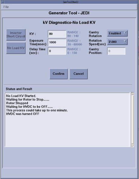
- Perform ROTATING No Load KV testingRun the No Load kV test using the following parameters: kV = 80, Exposure time (msec) = 1000, Gantry Rotation = Enabled, Rotation Speed (sec) = 2.000.
Figure 1. Rotating No Load KV Test
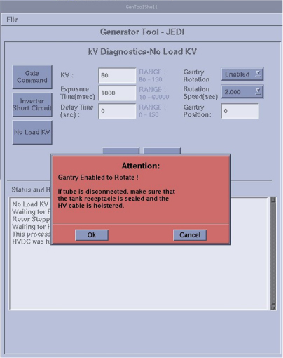
- Click Confirm button. Then attention
box will show up: Gantry Enabled to Rotate, Press OK button, it will start to rotate and scan.
Figure 2.
- Run the diagnostic. Verify:
-
No error is reported on the console
-
inverter gate_cmd board Leds DS101, DS102, DS201, DS202 are lit : IGBTs gate drive supply is working properly
-
- If the latter part of the test passes, along with the “Shorted Inverter Test ”, the system more than likely has a tube or HV cable problem.
Finalization
- Turn OFF HVDC ENABLE, AXIAL DRIVE ENABLE, and 120 VAC ENABLE switches on Service Switch.
- Remove High Voltage Terminal Plug and perform Securing HV Cable.
- Turn ON 120 VAC ENABLE, AXIAL DRIVE ENABLE, and HVDC ENABLE switches on Service Switch.
- Press ESTOP RESET on Service Switch panel and wait until scan hardware is reset.
- Perform System Reboot.
note:
System Reboot is required to reset the JEDI software expected load capacitance value. If the System is not rebooted, a Wrong High Voltage Capacitance Measured type error may occur.