- Topic ID: id_11038747
- Version: 3.0
- Date: Apr 22, 2019 12:55:44 AM
Intercom Board Replacement
Prerequisites
Overview
Procedure
- Remove right side cover.
- Stop the rotor of X-ray tube in case of Liquid Bearing Tube before HVDC off. Refer to Liquid Bearing Tube Rotor stop procedure for details.
- notice
- Turn off the three (3) main power switches (Axial
Drive, HVDC, 120VAC) on the Service Switch Panel.
Figure 1. Intercom Board location
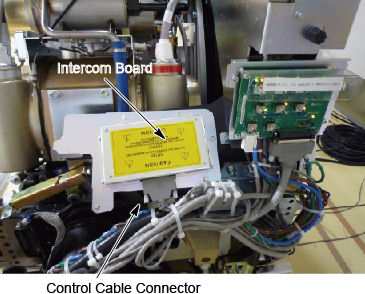
- Disconnect the control cable.
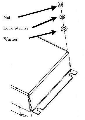
- Remove the cover assembly by removing 2 nuts and washers from
one side and loosening the 2 on the other side.note:
Be careful not to lose the nuts and washers. Also notice that the flat washer is installed first, then the lock washer and then the nut.
Figure 2. Hardware order
- Remove 4 screws that secure the intercom board to the cover.
- Install the new intercom board in reverse order. Verify that J2 jumper is in auto position.
 |
Finalization
- Perform the Intercom board check and adjustment defined by Intercom Adjustment.
- Make sure cover is tightened if removed for adjustments.