- Topic ID: id_17479152
- Version: 3.0
- Date: Jun 10, 2020 2:24:32 AM
Gantry Tilt Inclinometer Replacement and Adjustment
Prerequisites
Procedure
- Remove Gantry right and left covers.
- Shut down all power of Gantry
 warning
- Remove the inclinometer cable which connected to TGPG board,
remove three Hex M3 screws and then remove the inclinometer from the
Gantry.
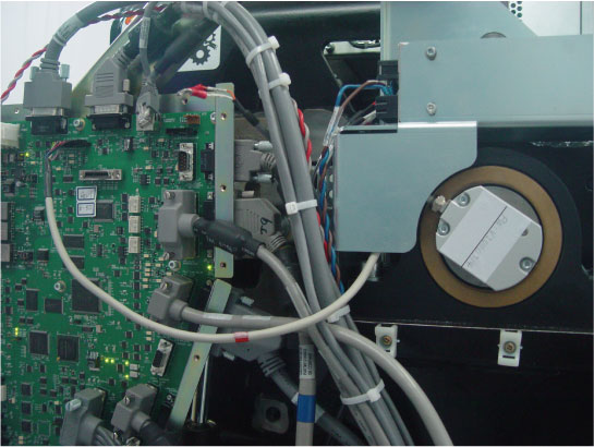
- Install the new inclinometer, connect the cable and fix the cable (red mark) to the bracket with ties.
- notice
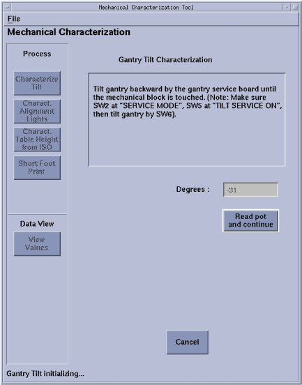
- Tilt gantry to 31 degree backward from service board (reach
the mechanical limit position), there are two test way for new inclinometer:note: Gantry Tilt Inclinometer Adjustment by using angle meter is the recommended test way.
-
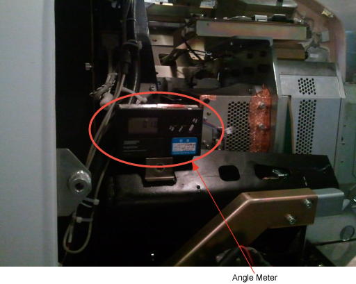
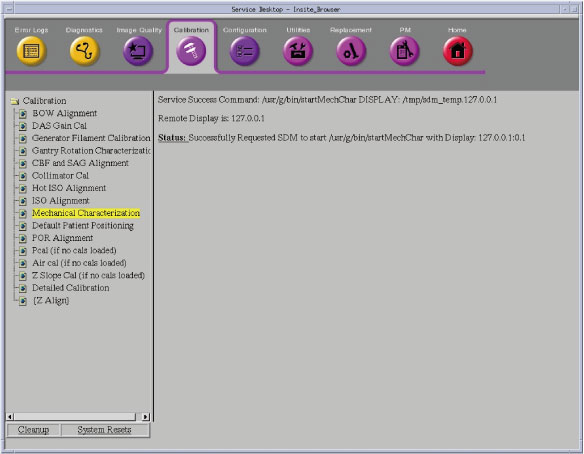
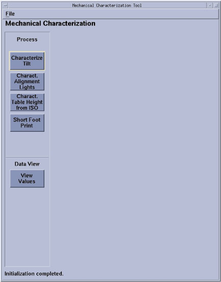
(For HAVE angle meter) Run the Gantry Tilt Characterization procedure from the Service Desktop, Calibration → Mechanical Characterization, Select the Characterization Tilt button, then click on Read pot and continue. Tilt the gantry to the Zero degree position, place the angle meter on the bracket as the Figure 2 shown. if the angle display from the angle meter is between -0.5 to + 0.5 degree, the replaced inclinometer passed; otherwise replace another inclinometer and repeat above procedure.
Figure 1. Tilt inclinometer check flowchart with angle meter
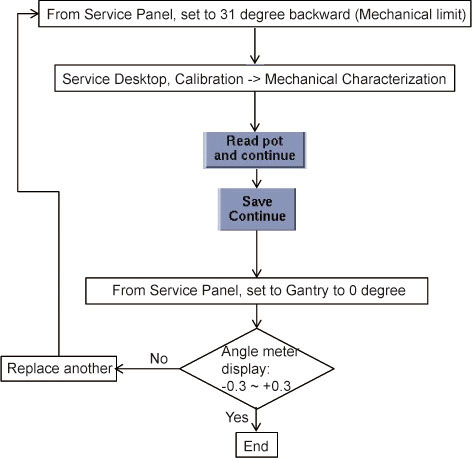
Figure 2. Angle Meter Location
-
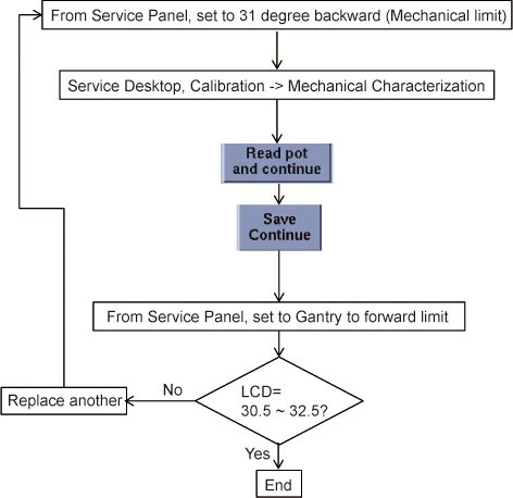
(For DO NOT have angle meter) Run the Gantry Tilt Characterization procedure from the Service Desktop, Calibration > Mechanical Characterization, Select the Characterization Tilt button, then click on Read pot and continue. tilt the gantry to the positive limit position, and at this time if the tilt display on gantry LCD between 30.5 degree to 32.5 degree, the replaced inclinometer passed; otherwise replace another inclinometer and repeat above procedure. Please refer to Figure 3 for detail
Figure 3. Tilt inclinometer check flowchart without angle meter
-
 |
Finalization
Tilt Gantry to 30 degree backward, then tilt to 0 degree then tilt to 30 degree forward to ensure there is no interference.