- Topic ID: id_17479546
- Version: 2.0
- Date: Jun 10, 2020 2:30:17 AM
Gantry Stationary (CFC) Fan Control Board Replacement
Prerequisites
Overview
This procedure defines the steps necessary to replace the stationary side Fan Control Module.
Procedure
- Remove the gantry right side cover and disable “Axial Drive”, “HVDC” and “120VAC” switches from the service switch panel.
- Remove the gantry left side cover, the CFC module is located on the left side of the gantry.
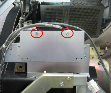
- Loosen two screws to remove the CFC housing cover.
Figure 1. CFC Module
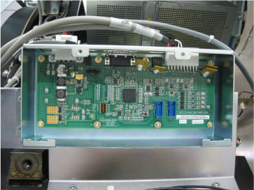
- Disconnect cable connectors from the CFC board J1, J7 and J4T.
Figure 2. CFC Board
- The CFC board is secured to housing with 8 screws, remove all screws with a hex wrench.
- Remove the defective CFC board and get the new one from anti-static bag.
- Install the new CFC board using the 8 screws.
- Reconnect all cable connectors removed, reference section above.
- Turn ON “Axial Drive”, “HVDC” and “120VAC” switches.
- Verify that the CFC board is operating normally.
- Install the CFC housing cover, and restore the gantry to original configuration.
Finalization
- Monitor the operator message area until the system indicates the detector temperature has returned to normal.
- Perform a Fastcal from the Daily Prep button on the Operator console.
- Perform a Quality Assurance Test from the Functional Checks menu of the service manual to ensure system operation.