- Topic ID: id_17479579
- Version: 3.0
- Date: Jun 10, 2020 2:30:11 AM
Gantry Front Cover Removal and Re-Install
Prerequisites
Overview
This procedure explains how to remove and re-install the CT Gantry front cover.
1 Redesigned Front Cover Dolly Setup
Procedure
 danger
- notice
- Arrange Dolly sections for assembly. The base and post can be
assembled only one way. Refer to Figure 1 and Figure 2.
-
The base uses two (2) palm screws to clamp the four (4) legs in the open or usage mode.
-
The base also uses the same palm screws to prevent the legs from falling in storage mode.
-
The top post can be inserted in either base and is keyed for proper engagement.
-
The top post locking pin prevents the sections from separating during usage.
Figure 1. Redesigned Front Cover Dolly in Storage Mode
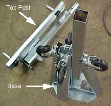
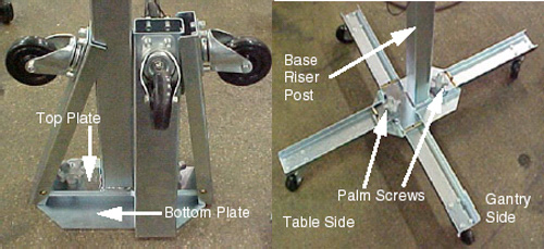
Figure 2. Redesigned Front Cover Dolly Base Assembly
-
- Unfold the base legs by loosening both palm screws to the top of their travel.
- Carefully unfold the legs so that the castors touch the floor.
- Tighten the palm screws to clamp the legs between the base top
and bottom plates.note: Lifting the base by the riser post while leaving the castors on the floor will ease palm screw tightening. Reference Figure 2.
- warning
- Insert top post into the base riser post. Align the key for complete engagement.
- Insert top post locking pin to secure both top and bottom sections.
- Reverse above steps to disassemble.note: For base storage only one (1) palm screw needs to be tightened. This will engage the bottom base plate and the leg ends preventing the legs from unfolding during transport and storage.
 |
2 Removal
Procedure
- Position the table at its lowest position.
- notice
- Remove gantry side and top covers, if you have not already done so.
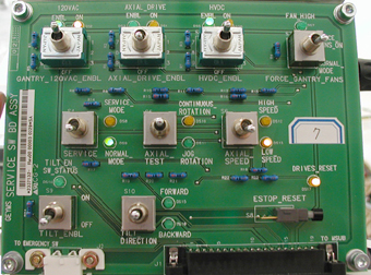
- Verify the three (3) power switches have been turned OFFFigure 3.
Figure 3. Service Switch Panel
- Assemble the front cover dolly.
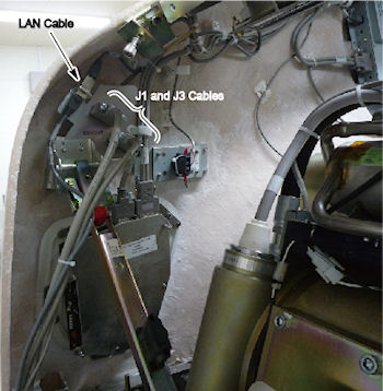
- Detach front cover J1 and J3 and LAN cables.
Figure 5. Front Cover Cables
- Remove the Mylar (scan) window.
- Remove front cover.
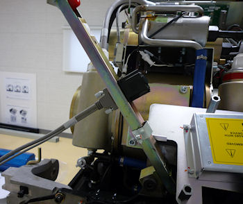
- Disengage upper cantrell bracket on right side of the cover.
Figure 6. Releasing Cover Brackets
-
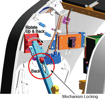
Disengage the locking mechanism on the upper cantrell brackets by using your thumb to slide the trigger (red lever) back. This will release the locking mechanism and allow the cantrell to be rotated upwards with steady and firm pressure.
-
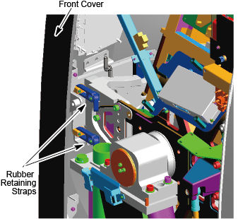
Disengage the rubber retaining straps on right side. See Figure 7. You may find it helpful to lift “up” on the cover to align the stud while attaching the rubber retaining straps.
Figure 7. Rubber Retaining Straps and Cover Locking Mechanism
-
- Disengage the left side of the front cover
-
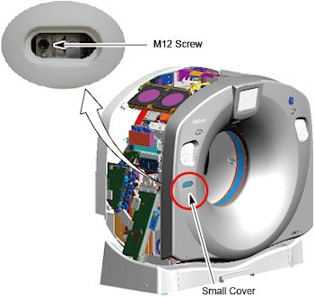
Remove the small cover from the front cover.
-
Loosen M12 screw.
Figure 8. Disengage the Left Side of the Front Cover
-
- Lift and rotate cover locking arm to unlocked position.
- Disengage upper cantrell bracket on right side of the cover.
- Rotate front cover away from gantry.
- Move front cover away from gantry, leaving space (about 5 feet) between cover and gantry.
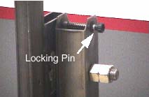
- Pull the locking pin and rotate front cover away from gantry.
Place locking pin in one of the side dolly perforations. See Figure 9.
Figure 9. Releasing Front Cover Dolly Hinge
- Continue cover removal per Figure 10.
Figure 10. Front Cover Removal Sequence
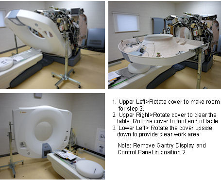
- Rotate the cover horizontally and move it back and over the table to a safe location. Once in a safe location, you may over-rotate the cover full vertically but upside down.
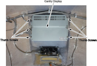
- Remove the gantry xtream display and control assemblies from
the front cover and place then into their service positions if scan
is required during maintenance.
- Disconnect cables from the gantry xtream display.
- The gantry xtream display is held in place with (6) thumb screws.
Use a flat-blade screwdriver to remove the Display. See Figure 11.
Figure 11. Gantry Display Removal
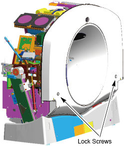
- Loosen two lock screws of the rear cover.
Figure 12. Lock Screws of the Rear Cover
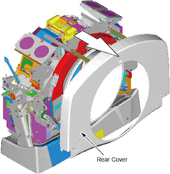
- Side the rear cover backward.
Figure 13. Rear Cover Slide
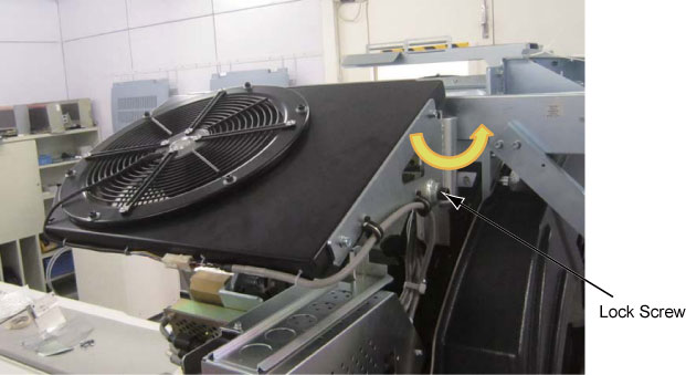
- Loosen the lock screw of the right top fan of the gantry, and
rotate the right top fan.
Figure 14. Top Fan Rotation
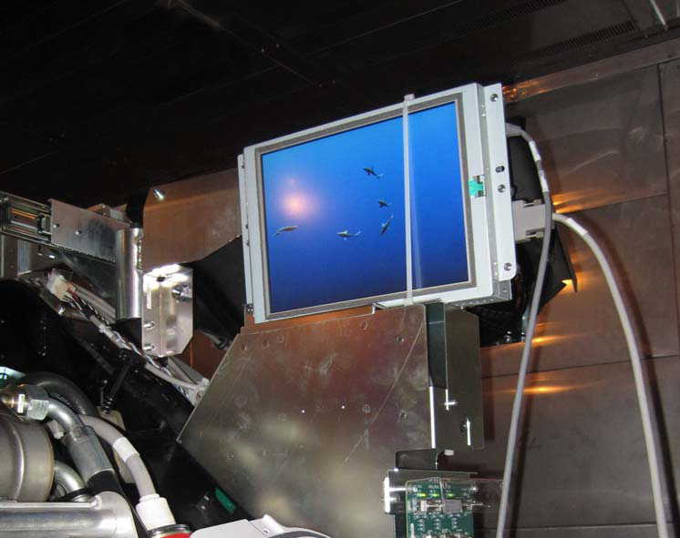
- Place the gantry xtream display in the bracket on the right
side of the gantry. See Figure 15.
Figure 15. Gantry Display Service Mounting Location
- Connect the cables to the gantry xtream display.
- Remove right gantry control assemblies, and place it into its
service position.
- Disconnect cables from the gantry control assemblies.
- Loose five (5) screws that fasten the control assemblies to the cover. See Figure 16. Keep one hand on the control panel at all times to prevent it from dropping to the floor.
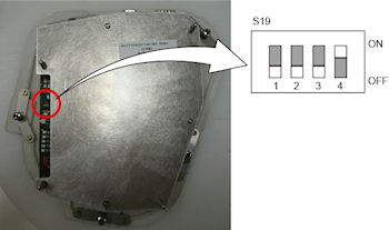
- Set dip switch s19-4 to ON position.
Figure 16. Dip Switch S19 - 4 Setting
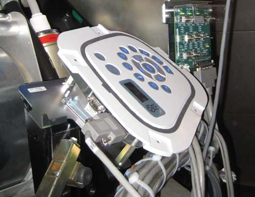
- Align the ball studs with their associated receivers and snap
into place.
Figure 17. Control Panel Service Position
- Connect FCVR BKHD J1 cable to terminator located on the cantrell
arm. See Figure 18.
Figure 18. Gantry Service Mode Cable Terminator
 note: There are 3 cables, each of which is unique. The ribbon cable is not used in the Service configuration. The other 2 cables will only fit in the terminator or the control panel, not both.
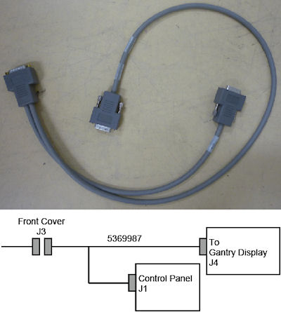
 - Connect the FRT CVR J3 cable to the extension cable 5369987
and connect the other end of the connectors to display and control
panel.
Figure 19. FRT CVR J3 Cable
|
3 Installation
Procedure
- Remove the gantry display and control assemblies from their
service positions and reattach them to the gantry cover.
- Disconnect cables from Display and Gantry Control Panels.
- Install Gantry Display in front cover. Secure the 6 thumbscrews. With a flat-blade screwdriver, gently tighten past finger-tight.
- Set the dip switch on the control panel to original position.
- Install the gantry control panel, Secure the 5 screws.
- Reattach cables.
- notice
- Rotate gantry front cover back to its vertical position.
- Attach the front cover.
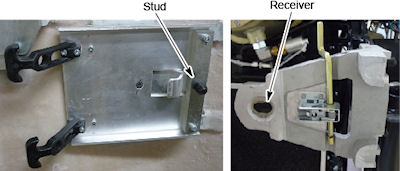
- Align the studs on both sides of the front cover with each associated
receiver. Receiver is located on the gantry frame.
Figure 20. Cover Stud and Mounting Bracket Receiver
- For Right Side:
Insert the stud on one side into its associated receiver and attach the rubber retaining straps.Then insert the stud on the other side into its associated receiver and attach its rubber retaining straps.
You may find it helpful to lift "up" on the cover to align the stud while attaching the rubber retaining straps.
- Reattach upper cantrell brackets on right side.
- For Left Side:
Insert the stud onto it's associated receiver and fasten the M12 screw and install the small cover (see Figure 8).
- Align the studs on both sides of the front cover with each associated
receiver. Receiver is located on the gantry frame.
- Remove dolly, disassemble and store safely away for later use.
- Reattach cables to cover.
- Re-install the Mylar (scan) window.
|
4 Finalization
Procedure
- Continue with other cover installation procedures as necessary. When AC power is restored to the system, prior to enabling axial drive or HVDC, remember to rotate the gantry by hand to ensure there is no interference between covers and rotating components.
- Verify all covers, especially side covers are properly secured.
- Ensure there is no interference during all tilt range.