- Topic ID: id_17479586
- Version: 2.0
- Date: Nov 19, 2019 11:09:53 PM
Fuse Box Assy Replacement
Prerequisites
1 Fuse Box Removal
Procedure
- Remove the gantry right side cover.
- notice
- Turn OFF Axial Enable, HVDC, and 120VAC switches on the Service Switch panel.
- Remove the gantry left side and top covers.
- Position the DAS at the 11 o'clock position.
- Cut tie-wraps holding cables to the DHCB (Detector Heater Control
Board) cover.
Figure 1. Cut Tie-wrap
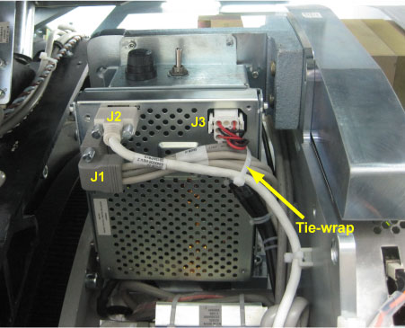
- Disconnect all cable connectors from the DHCB (J1, J2 and J3). (See Figure 1)
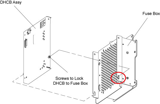
- Remove the DHCB Assy from the fuse box by unscrewing its four
screws.
Figure 2. DHCB Removal
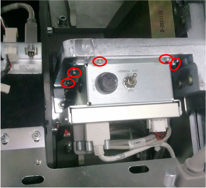
- Remove the fuse box with cables from the DAS mounting plate
by unscrewing its five M5 screws.
Figure 3. Fuse Box Removal
- Only slightly disengage the fuse box from the DAS mounting plate because of cables interference, then lift to show up the fuse box rear cover, cut any necessary tie-wraps.
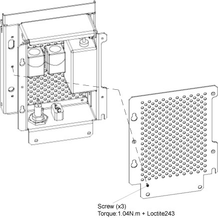
- Remove the rear cover from the fuse box by unscrewing its three
screws.
Figure 4. Remove Fuse Box Rear Cover
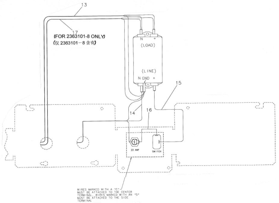
- Disconnect all associated terminals and cables.
Figure 5. Inside View of Fuse Box
 |
2 Fuse Box Installation
Procedure
- Get the new fuse box and reconnect terminals/cables.
- Reinstall the rear cover by screwing its three M3 screws. (Torque: 1.04N-m + Loctite 243).
- Remount the fuse box to DAS mounting plate. (Torque: 4.6N.m)
- Reinstall the DHCB Assy.
- Reconnect all cable connectors to the DHCB (J1, J2 and J3) and retie cables with tie-wraps.
- Turn on Axial Enable, HVDC, and 120VAC switches.
- Restore the gantry to original configuration.