- Topic ID: id_17423479
- Version: 3.0
- Date: Jan 20, 2020 8:33:27 PM
Foot Switch Assembly Replacement
Prerequisites
Overview
Procedure
- notice
- Move the cradle to the OUT mechanical limit position by hand.
- Raise the Table to its highest position.note:
If the Table up/down movement is inoperative, use the service power cable to raise the Table (refer to Enforced Table Elevation).
- Remove power from Table by turning off “120VAC”, “Axial Drive” and “HVDC” switches on the service switch panel."
- Remove the following cover from the Table:
-
Rear Bottom Cover (Refer to Table Covers Removal)
-
Front Bottom Cover (Refer to Table Covers Removal)
-
Protect Cover (Three(3) Screws)
-
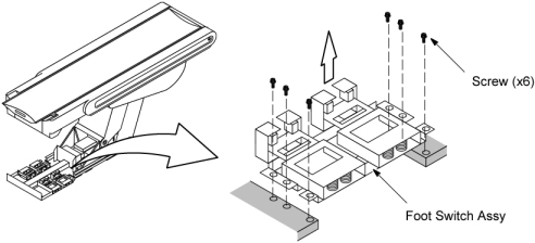
- Disconnect the two cables from the Foot Switch Assy.
- Remove the Foot Switch Assy by unscrewing its six screws.
Figure 1. Foot Switch Assembly
- Install the new Foot Switch Assy by referring toStep 6 through Step 5.
- Restore the Table to original configuration.
 |
Finalization
No finalization steps.