- Topic ID: id_17479547
- Version: 1.0
- Date: Aug 28, 2018 3:55:39 PM
DoD57 DAS PS Assembly Replacement
Prerequisites
Overview
This procedure defines the steps necessary to replace the DoD57 DAS PS assembly.
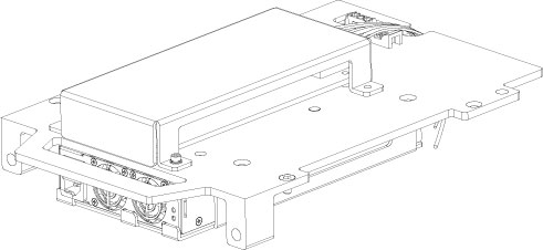
Figure 1. DAS PS ASM
Procedure
- Move the table cradle to the home position, and position the table to its lowest elevation.
- Remove the gantry right side cover and disable “Axial Drive”, “HVDC” and “120VAC” switches from the service switch panel.
- Remove the gantry left side, top and front covers, refer to Replacement > Gantry > Enclosure > Cover Removal Procedure.
- Switch ON “120VAC”, press Reset push button on the bottom right of the service switch panel.
- Position the DAS at the 12 o’clock position, and lock the gantry in position using the rotational lock.
- Switch OFF “120VAC”.
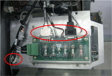
- Disconnect all cable connectors from the fuse board and power
supply.
Figure 2. Disconnect the Cable Connectors
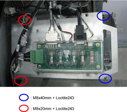
- Disassemble the power supplier assembly from the gantry frame
by unscrewing four M8 mounting bolts, then put it on an ESD pad..
Figure 3. DAS PS Assembly Removal
- Get the new DAS PS assembly and slide into place.
- Secure the DAS PS assembly to the gantry frame by using four M8 screws. (Torque: 19.2N-m)
- Reconnect all cable connectors to the fuse board and power supply.
- Disengage the rotational lock.
- Turn ON “Axial Drive”, “HVDC” and “120VAC” switches.
- Perform functional check by referring to DAS 48V Power Supply Checks.
- Restore the gantry to original configuration.
Finalization
- Perform a System Scanning Test from the Functional Checks menu of the service manual to ensure system operation.