- Topic ID: task_ssc_d2h_m3b
- Version: 5.0
- Date: Feb 22, 2022 12:50:57 AM
Depth Camera Calibration
Prerequisites
Overview
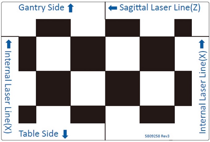
Figure 1. Camera Calibration Tool
Procedure
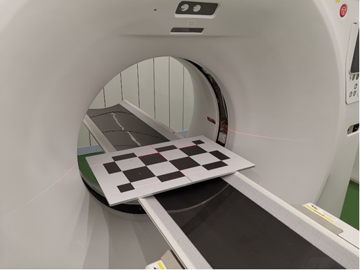
- Move cradle toward Gantry to the end position and turn on the alignment lights. Then put Camera Calibration Tool on the cradle, adjust Table height and cradle position.
Figure 2. Initial Position of Camera Calibration Tool before Adjustment
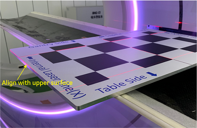
- Adjust Table elevation so that the upper surface of the Camera Calibration Tool plate is leveled at the isocenter height, for both left and right sides.
Figure 3. Camera Calibration Tool Position Alignment (Y axis)
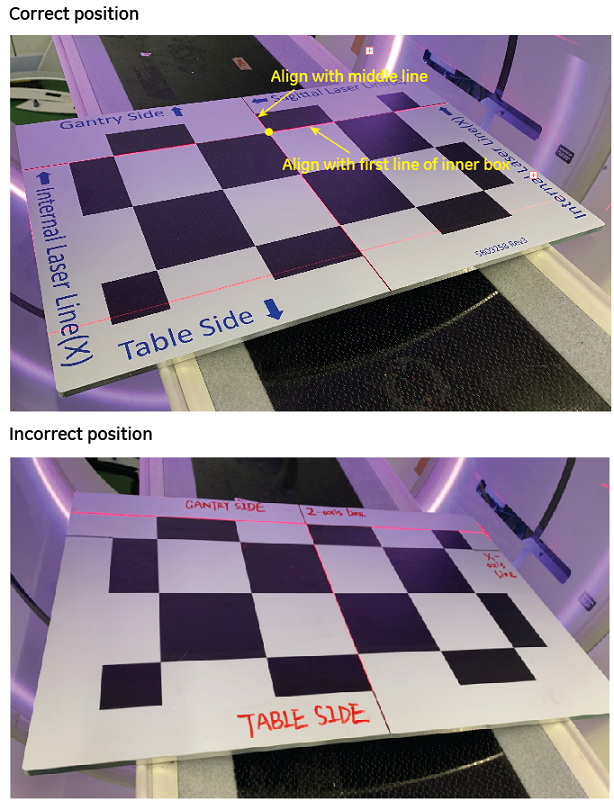
- Align the grids on the tool plate to the lights as shown in Figure 4. The operation process is as follows.
- Align the inner landmark laser with the first line of the boxes on the Camera Calibration Tool, and
- Align the center laser with the center line of the Camera Calibration Tool. The actual positioning on site is like Figure 5.
Figure 4. Camera Calibration Tool Position Alignment Requirement (X axis and Z axis)
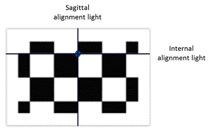
Figure 5. Camera Calibration Tool Position Alignment (X axis and Z axis)
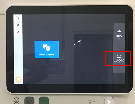
- Press the [Inner Landmark] button on the control panel so the cradle position reads in AIOC becomes 0 as Figure 6 shows. Then move cradle out to Z position at 1400mm. (DO NOT change table height).
Figure 6. Initial Position of Camera Calibration Tool after Adjustment
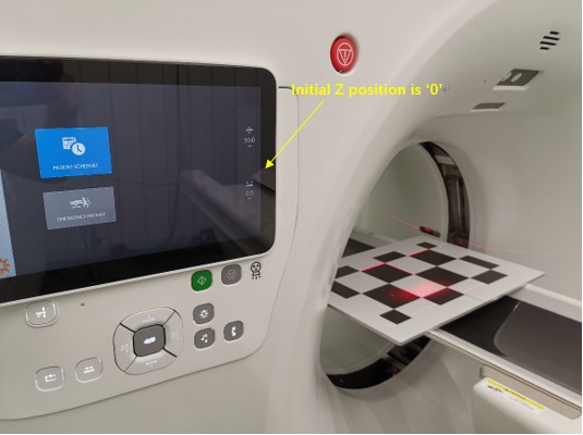
Figure 7. Cradle Position 1400mm
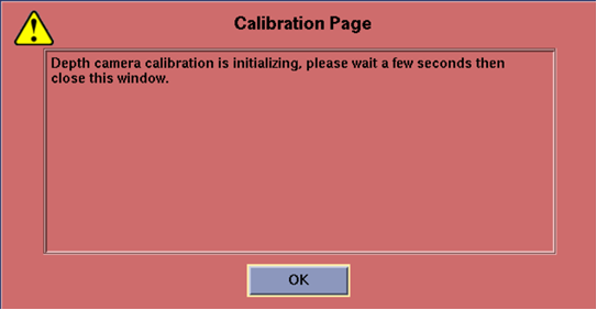
- Plug in SSA Class M hard key or SSA A2 license installed, launch CSD and select [Calibration] Tab to find [Depth Camera Calibration] menu. Click [Depth Camera Calibration], if the Calibration Page window pops up, click [OK] to close it.
Figure 8. Calibration Page
- Click [Start in Safe Mode] button, as depicted in Figure 9.
Figure 9. CSD Screen - GE Class M Service Key is plugged in or Class A2 License is installed
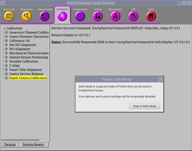
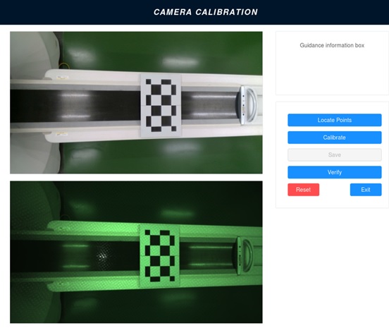
Figure 10. Initial Camera Screen
- Click [Locate Points] button (1) for the first time, and 15 points should be determined on the calibration tool and displayed on the screen (2), like Figure 11 shows.
Figure 11. Camera Screen - First Locating
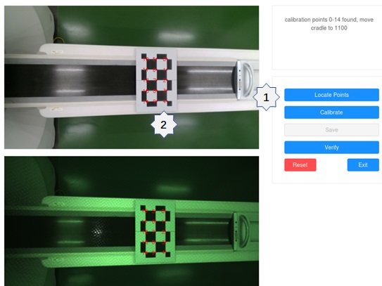
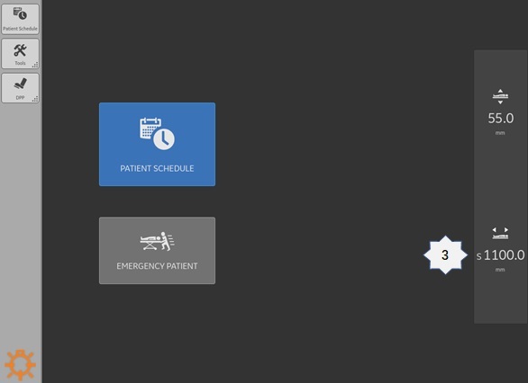
- Move the cradle to Z position at 1100mm (3) with the same Table height.
Figure 12. Current Table Position 1100mm
- Click [Locate Points] button (4) for the second time. There should be 30 points determined on the calibration tool and displayed on the screen (5), like Figure 13 shows.
Figure 13. Camera Screen - Second Locating
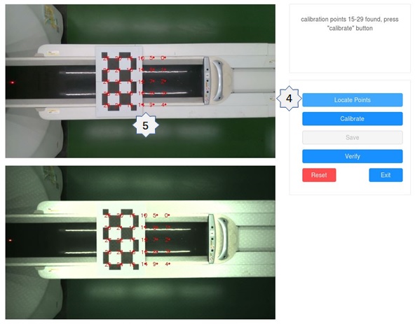
- Click [Calibrate] button, the screen should notify you calibration done. The screen displays: calculation done, press "save" button now.
- Click [Save] button to save results and click [Verify] button to verify results. The screen displays: calibration result saved.
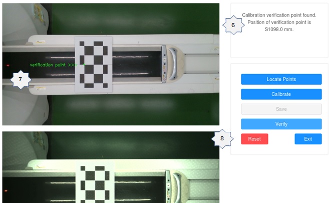
- There should be one verification point (6) determined on the calibration tool and displayed on the screen (7).
- Compare the output position of verification point (6) with the current table position (3). The difference should be within 10mm. If not, press [Reset] button (8), rework the calibration process from the start.
Figure 14. Calibration Verification Point Output Position
- Click [Exit] button to stop the calibration procedure and click
 on the top-right corner to close the calibration tool window.note: If you find depth/gantry calculation failed during depth calibration procedure, please redo the whole procedure.
Finalization
- Reboot CT system every time when finishing Depth Camera Calibration.
- Save system state.