- Topic ID: id_17423472
- Version: 4.0
- Date: Mar 6, 2020 10:02:00 PM
Cradle Belt Replacement
Prerequisites
Overview
Procedure
- notice
- Raise the Table to its highest position.note: If the Table up/down movement is inoperative, use the service power cable to raise the Table (refer to Enforced Table Elevation) .
- Move the cradle carriage to the mechanical OUT limit position by hand.
- Remove power from Table by turning off “120VAC”, “Axial Drive” and “HVDC” switches on the service switch panel.
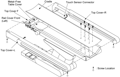
- Remove the following cover and component from the Table:
-
Top Cover R / L (Refer to Table Covers Removal)
-
Top Cover F (Two(2) Screws)
-
Cradle (Refer to Cradle)
-
Metal–Free Table Cover (Four(4) Screws)
-
Rail Cover Front (Left/Right) (Two(2) Screws x 2)
Figure 1. Table Covers Removal
-
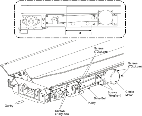
- Release belt tension:
- Measure the distance ‘D’ (between the pulley and cradle motor).
- Loosen 4 screws that fasten the cradle motor to the Table frame.
- Slide the cradle motor toward the Gantry, to remove tension from the drive belt.
- Loosen 4 screws that fasten the pulley to the Table frame.
- Slide the pulley toward the Gantry, to remove tension from the cradle belt.
Figure 2. Release Belt Tension
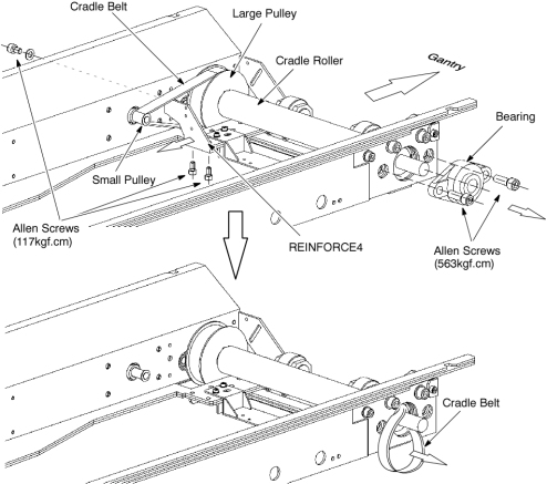
- Remove the cradle belt:
- Remove a bearing of the cradle roller from right side of the Table by unscrewing its 2 Allen screws.
- Remove a REINFORCE4 from the Table frame by unscrewing its 3 Allen screws.
- Remove the cradle belt from the small pulley and the large pulley.
- Pass the belt through the hole of the Table frame, and out of the Table.
Figure 3. Cradle Belt Removal
- Install the new cradle belt by referring toStep 6.d through Step 6.a.
(Properly position the new belt on and around the cradle pulley and the small pulley)
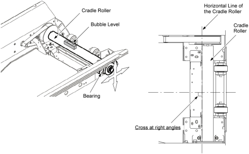
- Adjust position of the cradle roller:
- Loosen 2 Allen screws that fasten the bearing of the cradle roller to the Table frame.
- Place the bubble level at the position as shown in Figure 4.
- Level the cradle roller by moving the bearing.
- Tighten the 2 Allen screws (Torque: 50kgf.cm)
Figure 4. Position of the Cradle Roller Adjustment
- Put the cradle on the Table, and perform ‘GAP BETWEEN CRADLE AND CRADLE SUPPORT’ adjustment according to Align, Setup, Cals -> Table.
- After you install the new belt: (see Figure 2)
- Slide the pulley away from the Gantry, and verify no slack in the cradle belt.
- Perform ‘CRADLE BELT TENSION’ adjustment according to Align, Setup, Cals -> Table.
- Slide the cradle motor away from the Gantry, and adjust position of the cradle motor to meet the ‘D’ recorded at Step 5.a, and fix the cradle motor.
- Restore the Table to original configuration.
 |
Finalization
- Verify that the cradle moves In and Out normally.