- Topic ID: id_16157497
- Version: 3.0
- Date: Apr 22, 2019 12:56:35 AM
Breathing Light Assembly Replacement
Prerequisites
Overview
This procedure defines the process to replace the breathing light assembly on the front and rear cover.
Procedure
- Remove gantry right side cover.
Refer to
- Stop the rotor of X-ray tube in case of Liquid Bearing Tube before HVDC off. Refer to Liquid Bearing Tube Rotor stop procedure for details.
- Turn OFF the Axial Drive, HVDC and 120 VAC switches on the gantry’s Service Switch Panel.
- Remove the gantry left side cover, top covers and scan window.
- Remove the front (or bore) cover.
- On the back side of the front (or bore) cover, remove the cables
on the breathing light assembly.
Figure 1. Gantry Breathing Light Assembly
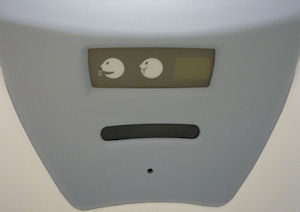
Figure 2. Breathing Light Assembly mounts
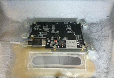
- With a Phillips-head screw driver, remove five (5) screws that fasten the breathing light assembly to the cover.
- Replace the breathing light assembly panel with the 4 screws and reconnect the 2 cables.
- Install the gantry front (or bore) cover, scan window, top covers
and left side cover.
Refer to
- Enable 120 VAC HVDC and Axial Drive service switches from the service switch panel. Press the table drives enable button on the lower right corner of the service switch panel.
Finalization
- Check the gantry displays during gantry power up to make sure the breathing lights turn on/off during the reset.
- Install the gantry right side cover.