- Topic ID: id_16158055
- Version: 2.0
- Date: Nov 7, 2019 8:54:16 PM
Beam on Window (BOW) Alignment Process
Prerequisites
Overview
The objective of this procedure is to put the detector in the correct position, assuming the tube is already in the correct position. This makes sure the X-ray Flux does not miss the detector.
Figure 1. BOW Flowchart
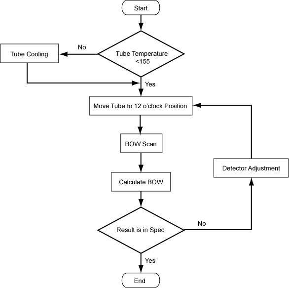
1 For Tube Change Only
Wait 90 minutes if the new tube had more than 25 Kilo Joules of energy input, [KV x mA x Sec ÷ 1000] within the last 30 minutes prior to the start of system alignments. If a tube heat soak has been performed you must wait a minimum of 6 hours before system alignments can be performed.
2 Confirm Tube Cooling
When performing alignments, wait at least 15-30 minutes between scans to prevent unnecessary adjustments.
3 Preparation
Procedure
- Move the cradle OUT to its fully retracted position (farthest from gantry) and position the table to its lowest height.
- Remove the gantry right side cover.
- Turn OFF “Axial Enable”, “HVDC” and “120VAC” switches on the service switch panel.
- Remove the gantry covers as required.
- Turn ON “HVDC”, “Axial Enable” and “120VAC” switches.
4 Adjustment Procedure
Procedure
- Select Service → Calibration → BOW Alignment to enter ‘Beam on Window’ UI.
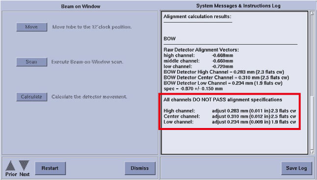
Figure 2. Beam on Window
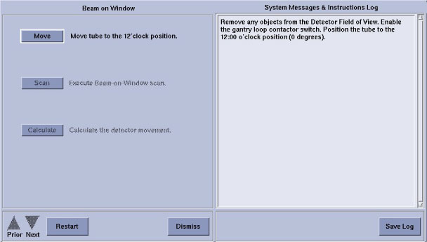
- Remove any objects from the detector field of view.
- Click Move to enter ‘Tube Position’
window.
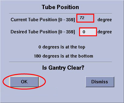
- Check ‘Current Tube Position’, if not 0 deg, input 0 in ‘Desired Tube Position’. Then click
OK.
Figure 3. Tube Position
- After ‘Current Tube Position’ displays 0 degree,
click Dismiss to quit this window.
Figure 4. Tube Position OK
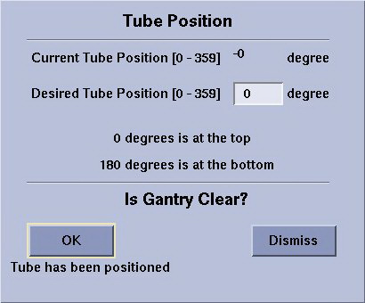
- Check ‘Current Tube Position’, if not 0 deg, input 0 in ‘Desired Tube Position’. Then click
OK.
- Click Scan to execute Beam–on–Window scan.
- Click Calculate to calculate the detector
movement, and the account result displays on the monitor.
Verify values are within specification -0.970mm ± 0.150mm.
-
If BOW is within spec, “All channels PASS alignment specifications” displays, DO NOT adjust anything.
-
If BOW is out of spec, continue the following steps to execute the detector adjustment.
-
- Adjust the detector position.
- Turn OFF “HVDC”, “Axial Enable” and “120VAC” switches on the service switch panel.
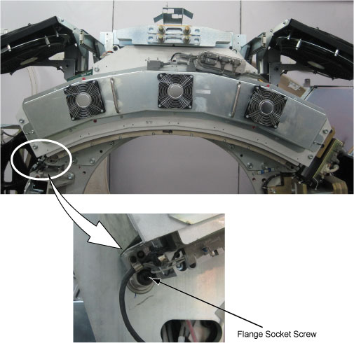
- Loosen two flange socket screws in both sides of the detector
and the lock screw in the middle of the detector.
Figure 5. Flange Socket Screws and Lock Screw
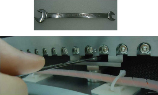
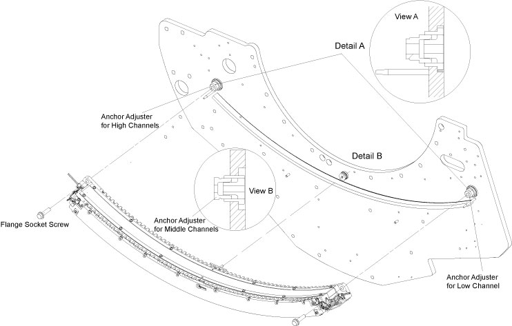
- Turn three anchor adjusters (See Figure 6) to shift the
detector offset within specification along the Z-Axis according to
the calculative result displayed on the monitor screen.note:
One turn
 = 6 Flats
-
Clockwise: BWD, away from the table
-
Counterclockwise: FWD, towards the table
Figure 6. Beam on Window Adjustment
-
- Secure the lock screw with torque 13.5N-m and two flange socket screws with torque 30.5N-m which were loosened in Step 6.b.
- Turn ON “Axial Enable”, “HVDC” and “120VAC” switches.
- Click Restart to repeat BOW procedure from Step 3 tdo Step 5.
- Click Save Log, then click Dismiss to quit BOW.
- Restore the gantry to original configuration and reinstall the table foot switch cover.