- Topic ID: id_17479476
- Version: 2.0
- Date: Nov 19, 2019 11:09:12 PM
Axial Drive Controller Replacement
Prerequisites
Overview
This procedure describes the steps necessary to install Axial Drive controller into the Danaher axial drive assembly. Refer to Figure 1 for a visual reference of the controller.
Figure 1. Axial Drive Controller
1 Preparation for Replacement
Procedure
- notice
- Remove gantry right side cover and disable axial drive, HVDC
and 120VAC service switches from the service switch panel. Remove
all system power at the Main Disconnect panel and use proper Lockout/Tagout
procedures.
Refer to Replacements > Gantry > Enclosure > Gantry Side Covers Removal and Re-install.
- Remove the gantry left side and top covers, scan window, and front cover. Connect the cover E-stop circuit to the terminators on the gantry.
- Remove the two cross screws from the n-shaped bracket.
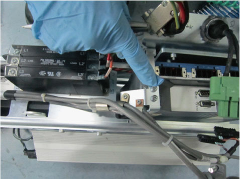
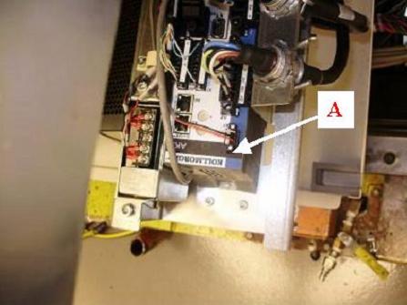
- Disconnect all cables from existing controller and remove controller
from axial drive assembly by removing the two screws attaching the
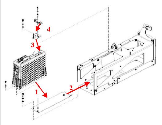
bottom bracket to the axial drive with a 5mm hex wrench. Refer to Figure 2.
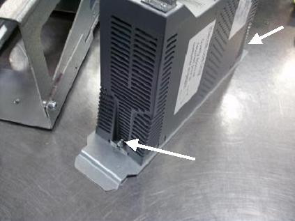
Figure 2. Removing Controller Assembly
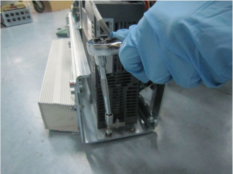
- Remove top L-shaped bracket from controller and axial drive assembly. Be sure to keep this bracket as it will be re-used for the installation of the new controller. Refer to Figure 3.
- Remove controller from bottom bracket using a 3mm hex wrench.
Be sure to keep the bottom bracket as it will be re-used for the
installation of the new controller. Refer to Figure 3 and Figure 4.
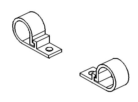
Figure 3. Placement of Brackets on Controller
 |
2 Installing controller on assembly frame
Procedure
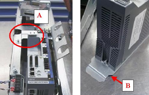
- Mount new controller to bottom bracket with two M4 nuts (with
lock washer) and two M4 flat washers (refer to Figure 4).
Figure 4. Mounting of controller onto bottom bracket
- Mount to bottom of drive assembly box with two M6 screws, lock
washers and flat washers. Refer to Figure 2and torque according
to the table below.
- Mount top (L-shaped) bracket onto controller with an M4 screw, lock washer and flat washer. Refer to Figure 3 for placement of bracket.
- Mount two plastic cable guides to the top of the second bracket with an M4 screw, lock washer and flat washer each.
3 Cable Installation and Routing
Procedure
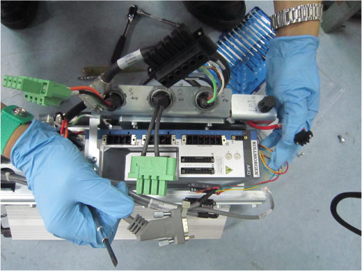
- Connect axial drive power cable from terminal strip into the X4 port of the controller. Refer to Figure 7.
- Connect resistor assembly cable to X3 port of the controller from underneath box. Refer to Figure 7
- Connect motor power cable from the 2010 Axial Drive motor to
the X2 port of the controller. Refer to Figure 7.
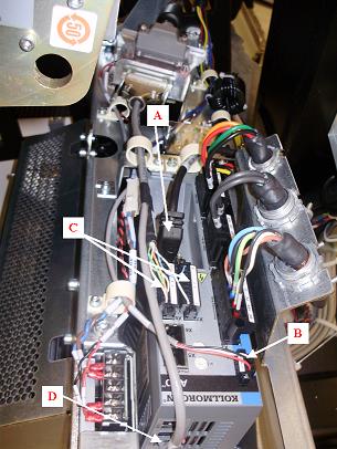
Figure 7. Routing of axial drive power cable, brake resistor cable and motor power cable
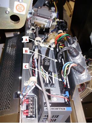
- Connect feedback cable from motor to X10 port of the controller. Refer to Figure 8.
- Connect cable from KIM board to X1 port of the controller. Refer to Figure 8.
- Connect two boxed ends of KIM com. cable into X7 and X8 ports
of the controller. Refer to Figure 8.note: The pins are positioned so that ends will only go in one way.
- Connect third end of this cable into X12 port of the controller.
Refer to Figure 8.
Figure 8. Routing of feedback cable, KIM to axial drive cable and KIM com cable
4 Reassemble gantry
Procedure
- Turn ON the 120VAC. An "o2" code should display on the axial
drive display screen. Refer to Figure 9
Figure 9. “o2” code on axial drive display
- Turn OFF the 120VAC
- Replace the right side tilting safety cover.
- Replace the front, top, and left side covers and the scan window.
- Turn on the 120VAC, axial drive and HVDC service switches from the service switch panel.
- Install the gantry right side.
5 Finalization
Procedure
- Run the System Scanning Test from the Functional Checks procedure list.