- Topic ID: id_11038672
- Version: 3.0
- Date: Jun 10, 2020 2:24:28 AM
Alignment Light Adjustment
Prerequisites
Procedure
- Remove gantry covers as required.
Refer to
- Remove cradle pad and associated accessories.
- Place head holder on the end of the cradle.
- Verify head holder is level side to side.
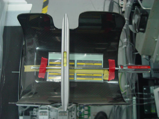
- Assemble washer and screwdriver and secure to head holder as
shown in Figure 1.
Figure 1. External Laser Alignment Jig Setup
 danger
- Turn on external laser light using gantry control panel.
- Adjust jig position such that:
-
External laser shine on the washer's edge center
-
Sagittal and Coronal lasers shine on the center of the screwdriver shaft
note:Chose either the left or right side of the jig as a reference for this procedure.
-
- When the external laser shine on the jig right position, press the Internal Landmark button to zero the cradle position display. control the table move 240mm toward gantry direction from gantry control panel .
- Select New Patient, Baby, 20.1 Service Generic Scan, Create
New Series, Scout.
- Confirm and Scan.
- Image Works, Browser Select Exam, Series, Image.
- Select Format one over one (lower left)note:
Both scout should now be displayed. Adjust the window and level setting so you can see the outline of the screwdriver handle. Click in a viewport to activate it, and select Grid.
The washer and screwdriver shaft need to be centered under the zero (0) grid lines. Both washer and screwdriver should also be parallel to the associated grid lines. See Figure 2.
Figure 2. Aligning the Laser Adjustment Jig to ISO Center and the Z-Axis
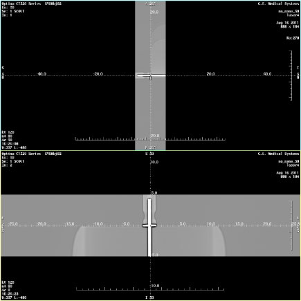
- Write down the error delta from the Zero (0) grid lines to the center of the screwdriver shaft and washer edge. Use measure distance if desired.
- According to the image, adjust the jig position at X (move the screwdriver), Y (move table) and Z (move table) direction to make sure the Jig on the ISO center and Z-axis center. DO NOT MOVE THE HEAD HOLDER.
- Select Repeat Series and scan.
- Repeat Step 9 through Step 15 until jig reference points are centered under the grid zero (0) lines.
- notice
- Press the Internal Landmark button to zero the cradle position display.
- danger
- Press the Alignment Lights button.
- danger
- Turn OFF Axial Enable switch.
- Adjust the internal laser to shine on the washer's edge center.
Reference external Laser chosen in Step 7 to shine on
the washer’s edge center. Reference Figure 3.
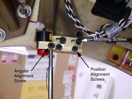
Mounting Screws Angular Alignment Screw Position Alignment Screws.
Figure 3. Laser Adjustment Screws
 note:
note:Properly adjusted Lasers will bisect the output port of the other 2 Internal lasers.
- Adjust the Sagittal and Coronal lasers so they shine on the screwdriver shaft at ISO Center. Set Coronal lasers as level as possible and Sagittal laser as parallel to the cradle as possible. Tracking adjustments will be performed in later steps.
- Move the cradle 240 mm out of the gantry, using the gantry control panel.
- Adjust the Reference external Laser to shine on the washer’s edge center.
- After Reference Lasers have been adjusted, raise and lower the table, and verify both the External and Internal lasers track the washer’s edge center.
- notice
- Repeat Step 20 through Step 24 as needed.
- Remove the screwdriver jig without disturbing the head holder.
- Now that the reference lasers have been set, use a piece of notebook paper to adjust the other lasers to coincide with the reference lasers. (see Alignment Lights Visual Checks).
- notice
- The last adjustment is the un-referenced Coronal laser to the Reference Coronal laser chosen in Step 7 (see Alignment Lights Visual Checks).
- Assemble the gantry.
 |
|
|
Finalization
- Perform Alignment Lights Visual Checks.